Numerical control machining center clamp

A machining center and fixture technology, used in manufacturing tools, metal processing equipment, metal processing machinery parts, etc., can solve the problems of automatic detachment of the workpiece, lack of anti-skid mechanism, and inability to automatically push the workpiece displacement, and achieve the effect of workpiece stabilization.

Active Publication Date: 2021-11-16
广西机电技师学院
View PDF10 Cites 3 Cited by
  • Summary
  • Abstract
  • Description
  • Claims
  • Application Information

AI Technical Summary

Problems solved by technology

[0005] In order to solve the above technical problems, the present invention provides a CNC machining center fixture to solve the problem that the existing machining center fixture lacks an anti-slip mechanism when it is in use and clamped in contact with an object, and cannot easily install an anti-slip fixing mechanism according to requirements. Moreover, when the existing fixture of the machining center is in use, when the workpiece is unclamped, it cannot automatically push the workpiece to move, and cannot automatically disengage the workpiece.

Method used


Image

  • Numerical control machining center clamp
  • Numerical control machining center clamp
  • Numerical control machining center clamp

Examples


Embodiment

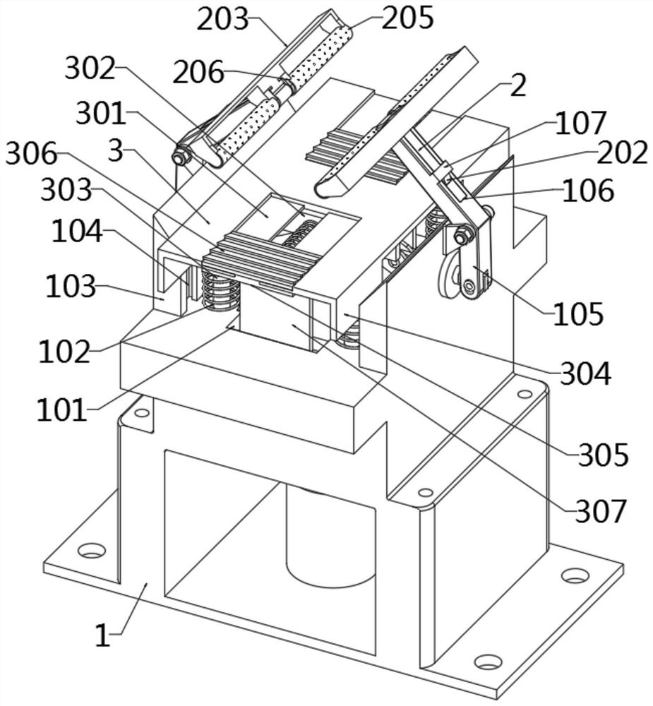
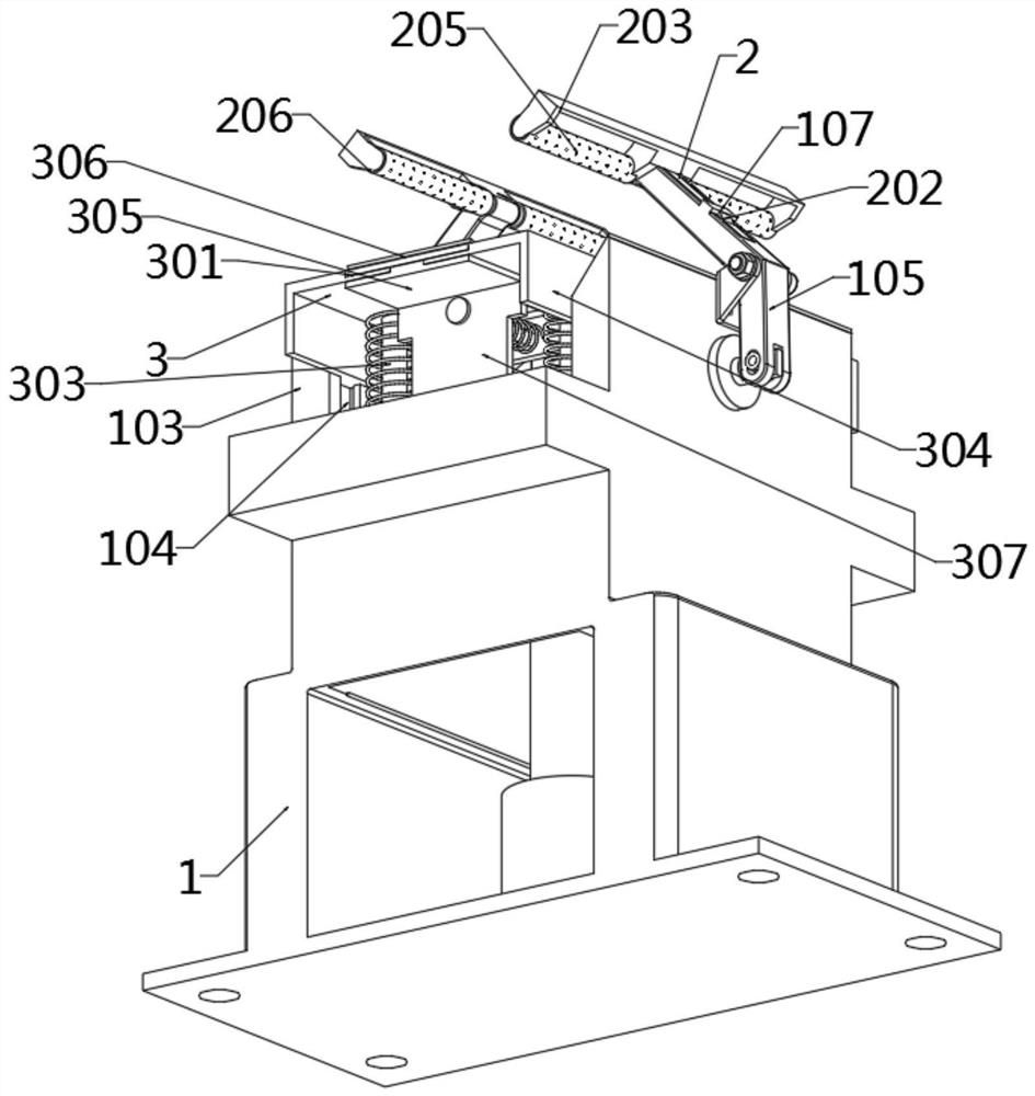
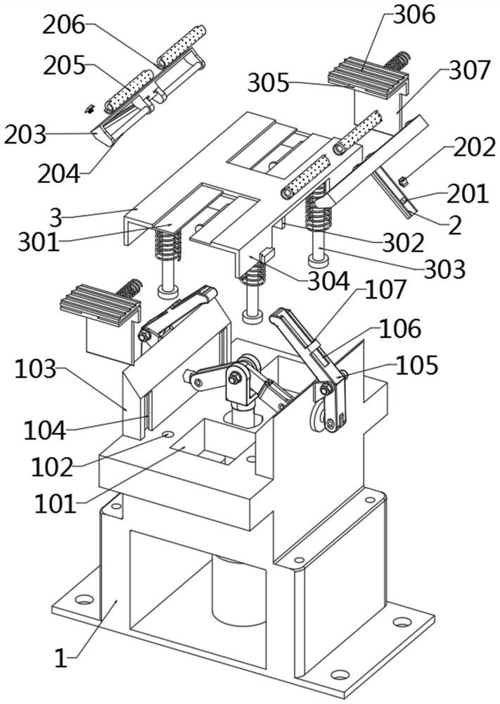
[0028] as attached figure 1 to the attached Figure 8 shown:

[0029] The invention provides a fixture for a CNC machining center, comprising a main body 1; the main body 1 is a T-shaped structure, the top of the main body 1 is provided with rectangular plates on both sides, an electric cylinder is installed inside the main body 1, and a pull rod is connected to the top of the electric cylinder, The pull rod is installed on the top of the main body 1, and the top of the main body 1 is installed with the moving plate 3; the plug-in 2, the plug-in 2 is a T-shaped structure, the plug-in 2 is inserted into the interior of the slot 106, and the plug-in 2 plays the role of connecting with the flip arm 105, And then follow the flip arm 105 to flip, so that the contact piece 205 can follow the contact and fix; the moving plate 3, the moving plate 3 includes a force displacement mechanism, the two ends of the moving plate 3 are equipped with a force displacement mechanism, and the mov...


PUM


Abstract

The invention provides a numerical control machining center clamp, relates to the field of clamps, and aims at solving the problems that when an existing machining center clamp is used and makes contact with an object for clamping, an anti-skid mechanism is lacked, and an anti-skid fixing mechanism cannot be conveniently installed according to needs. The numerical control machining center clamp comprises a main body and an inserting piece, the main body is of a T-shaped structure, rectangular plates are arranged on the front side and the rear side of the top end of the main body, an electric cylinder is installed in the interior of the main body, a pull rod is connected to the top end of the electric cylinder and installed at the top end of the main body, a movable plate is installed at the top end of the main body, and the inserting piece is of a T-shaped structure, and the inserting piece is inserted to the interior of an inserting groove. When an overturning arm is stressed to overturn and clamp a workpiece, the inserting piece can move along with the overturning arm, then a contact piece made of rubber materials can make contact with the workpiece in advance, the contact piece can deform in a self-adaptive mode, meanwhile, anti-skid contact can be carried out, and after the overturning arm is used for clamping, the workpiece can be more stable, and displacement and sliding cannot occur in the machining process.

Description

technical field [0001] The invention belongs to the technical field of fixtures, and more particularly, particularly relates to a fixture of a numerical control machining center. Background technique [0002] When the CNC machining center is used, it usually needs to be used with a fixture, so that the fixture can easily clamp the workpiece, which is convenient for the CNC center to process. [0003] For example, a CNC machining center fixture includes a positioning shaft, a base body, a thin-walled sleeve, and a medium. It is characterized in that: the base body is fastened on the positioning shaft by screws, and the base body and the thin-walled sleeve adopt an interference fit. There is a medium inside the wall sleeve, and under the action of the downward pressing force of the screw at the top of the base body, the medium lifts the outer wall of the thin-walled sleeve, so that the workpiece and the thin-walled sleeve are fastened together. The invention has the advantage...

Claims


Application Information

Patent Timeline
Patent Type & Authority Applications(China)
IPC IPC(8): B23Q3/06
CPCB23Q3/06
Inventor 蒋召杰杨智棠向金林韦杰唐杰陆宏飞汤一帆卢相昆覃燕珍伏海军
Owner 广西机电技师学院
Why Eureka
Try Eureka