
Sensor, method and system for remote detection of objects

A sensor and sensor element technology, applied in radio wave measurement systems, instruments, alarms, etc., can solve the problems of short working distance and high cost of the detection system

Inactive Publication Date: 2004-01-28
RSO
View PDF8 Cites 2 Cited by
  • Summary
  • Abstract
  • Description
  • Claims
  • Application Information

AI Technical Summary

Problems solved by technology

Naturally this means high cost
In addition, since the above-mentioned multi-element sensors work mainly through a magnetic or inductive circuit, the working distance of the detection system is very short

Method used


Image

  • Sensor, method and system for remote detection of objects
  • Sensor, method and system for remote detection of objects
  • Sensor, method and system for remote detection of objects

Examples


Embodiment Construction

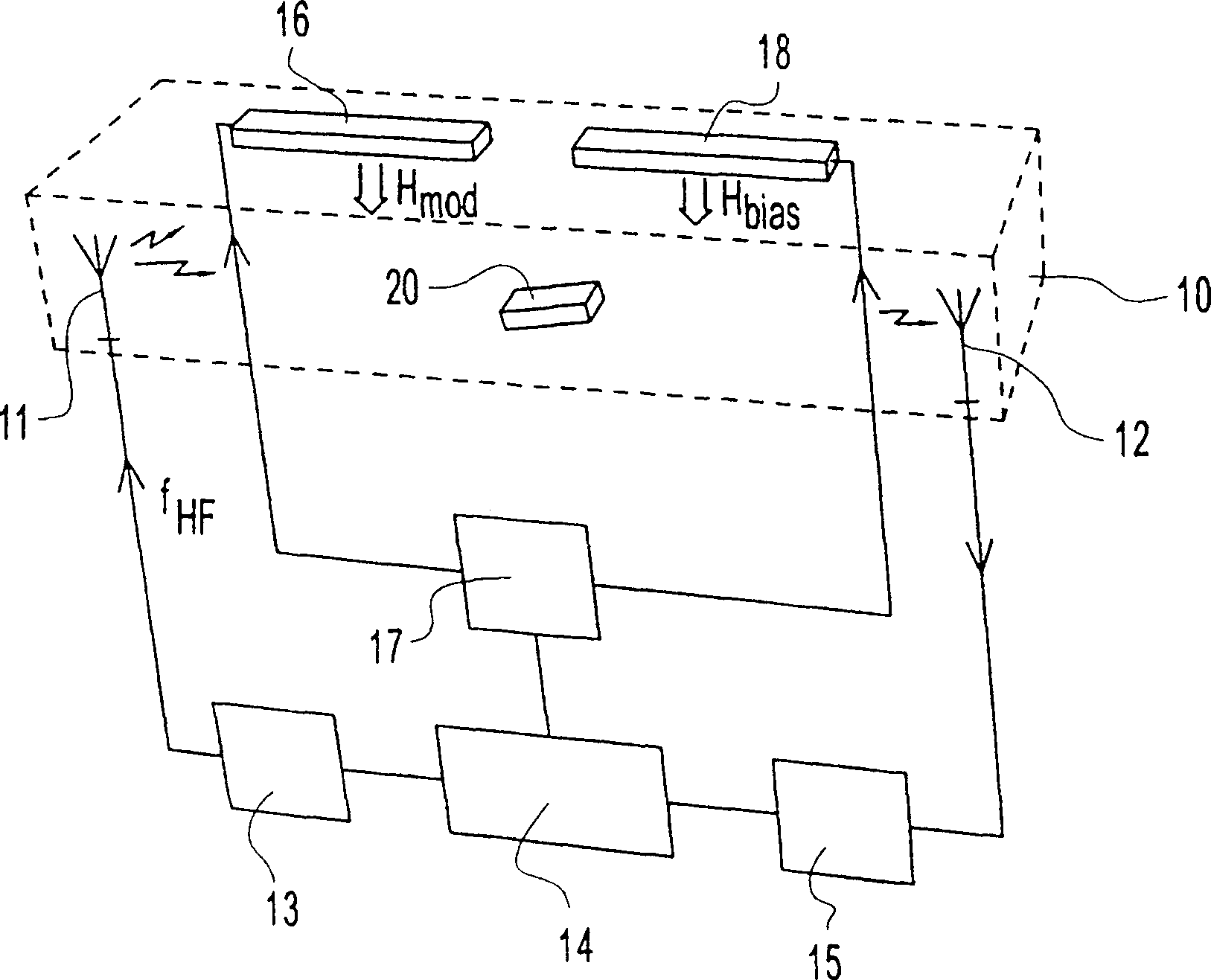
[0037] figure 1 A system for telemetry of objects is shown, in which the method and sensor according to the invention are applied. A transmitting antenna 11 and a receiving antenna 12 are arranged in the detection field. The transmitting antenna 11 is operatively connected to an output stage 13 which is in turn connected to a controller 14 . The output stage consists of various commercially available driver and amplifier circuits as well as for generating high frequency f HF A device for alternating current, when current is supplied to the transmitting antenna 11, the current flows back and forth through the antenna 11, wherein a high-frequency electromagnetic field is generated around the transmitting antenna 11. Use this electromagnetic field to excite the sensor existing in the detection area 10, so that the sensor emits an electromagnetic reply signal when receiving the electronic energy from the transmitting antenna 11, which is received by the receiving antenna 12. Th...


PUM


Abstract

The invention provides a method is provided for remote detection of objects, each object being provided with a sensor comprising at least two magnetic elements arranged in a predetermined mutual relationship representing an identity of the sensor. Electomagnetic signals are generated for exciting the sensor elements to produce electromagnetic reply signals. An amplitude of the electromagnetic reply signal from each sensor element is modulated by a first magnetic field having a magnitude-variant and a magnitude-invariant component. A second magnetic field is generated with rotating field vector. A frequency shift is detected in a component of said reply signal, when a magnitude-invariant component of said second magnetic field balances the magnitude-invariant component of said first magnetic field, wherein the respective sensor element is momentarily exposed to a resulting magnetic field with essentially no magnitude-invariant component. An orientation of the respective sensor element is determined from the orientation of the magnitude-invariant component of said second magnetic field, when said frequency shift occurs.

Description

technical field [0001] The present invention relates to a method and system for remotely measuring objects. Each object is equipped with a sensor, and the sensor includes at least two magnetic elements arranged in a predetermined relationship to represent the identity of the sensor, wherein the generated electromagnetic signal is used to excite the sensor element An electromagnetic reply signal is generated and the electromagnetic reply signal generated by each sensor element is modulated by a magnetic field having a variable and a non-variable. The invention also relates to a sensor for telemetry of an object, the sensor comprising at least two magnetic sensor elements arranged in relation to one another selected from a set of predetermined relations and representing the identity of the sensor or of an object connected to the sensor. Background technique [0002] Many applications require the reliable and contactless detection of the presence, identity or position of object...

Claims


Application Information

Patent Timeline
Patent Type & Authority Patents(China)
IPC IPC(8): G01V3/165G01V3/00G01V15/00G08B13/24
CPCG08B13/2474G08B13/246G08B13/2417G01V15/00
Inventor 卡尔·泰林
Owner RSO
Learn More