Solar intelligent street lamp adopting LoRa technology

A technology of smart street lamps and solar energy, applied in energy-saving lighting, components of lighting devices, support structures of photovoltaic modules, etc., can solve the problems of non-adjustable height and limited solar energy receiving efficiency, and achieve the effect of improving energy efficiency.

Pending Publication Date: 2021-11-16
中山市木林森户外照明有限公司
View PDF0 Cites 0 Cited by
  • Summary
  • Abstract
  • Description
  • Claims
  • Application Information

AI Technical Summary

Problems solved by technology

[0003] However, the height of the existing smart street lamps cannot be adjusted, and

Method used


Image

  • Solar intelligent street lamp adopting LoRa technology
  • Solar intelligent street lamp adopting LoRa technology
  • Solar intelligent street lamp adopting LoRa technology

Examples


Embodiment 1

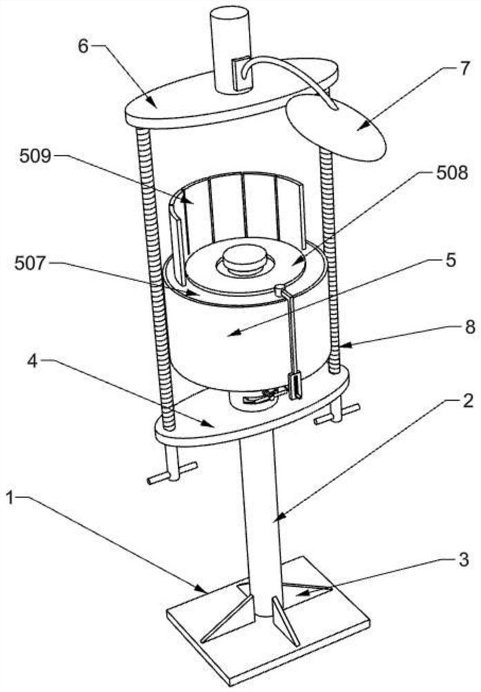
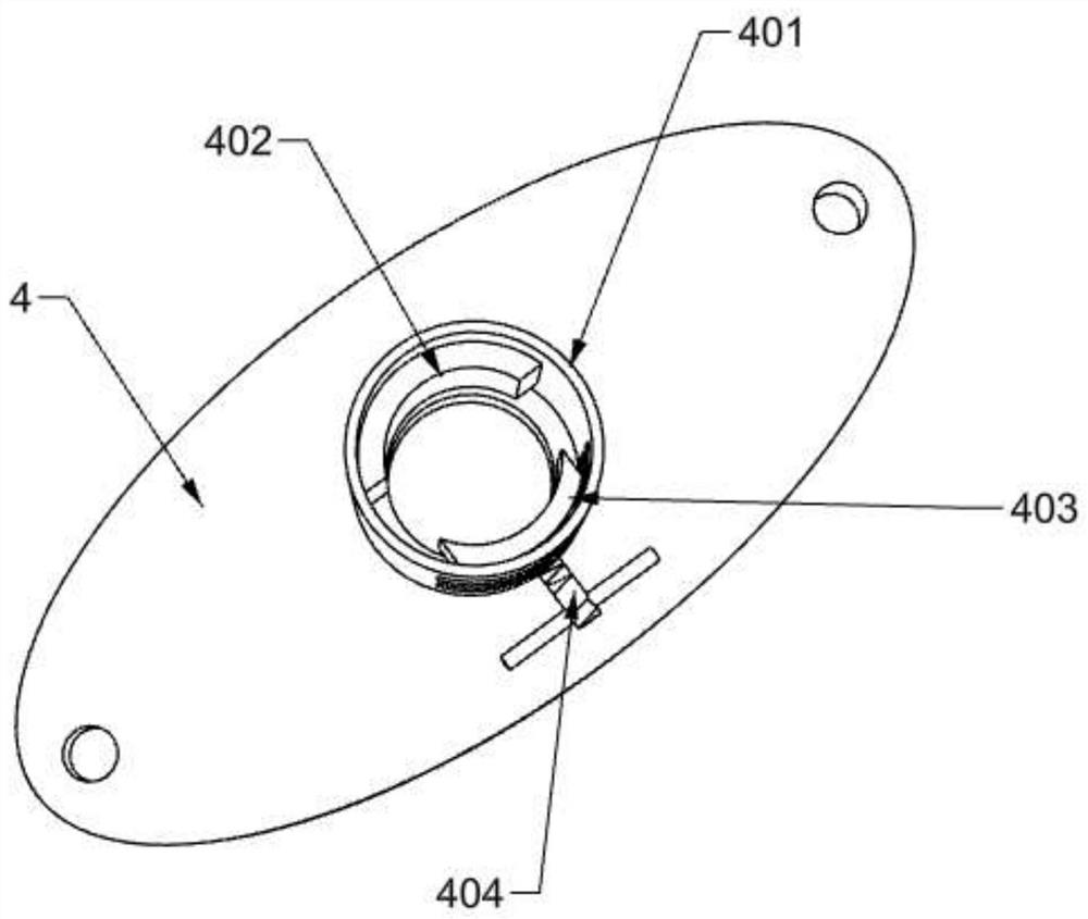
[0029] Example 1: Please refer to Figure 1~5 , in an embodiment of the present invention, a solar smart street lamp using LoRa technology includes a base 1, a reinforcing rib 3 is fixedly connected to the peripheral side of the fixing rod 2, and the lower end of the reinforcing rib 3 is fixedly connected to the base 1, and the base The upper end of 1 is fixedly connected with a fixed rod 2, the outside of the fixed rod 2 is provided with a clamping mechanism, the clamping mechanism includes a fixed plate 4, the two sides of the fixed plate 4 are screwed with an adjusting screw 8, and the upper end of the adjusting screw 8 is rotatably connected with a The upper end of the movable plate 6 is equipped with a lighting lamp 7; the upper end of the fixed plate 4 is fixedly connected with a fixed cylinder 401, one side of the fixed cylinder 401 is fixedly connected with a fixed block 402, and the other side of the fixed cylinder 401 is threaded. An adjusting bolt 404 is provided, a...

Embodiment 2

[0031] Example 2: Please refer to Image 6 , in the embodiment of the present invention, the upper end of the fixed rod 2 is horizontally fixedly installed with a reflector 515 , and the reflector 515 is located on one side of the solar panel 509 . More sunlight can be reflected to the solar panel 509 by the reflector 515 .

[0032] The working principle of the present invention is:

[0033] When the device is in use, it is used by an external controller and a power supply, and the user installs the device on both sides of the road. By turning the adjusting bolt 404, the fixing cylinder 401 can be clamped on the fixing rod 2, and by turning the adjusting screw 8, the The moving plate 6 rises or falls, which can change the working height of the illuminating lamp 7 .

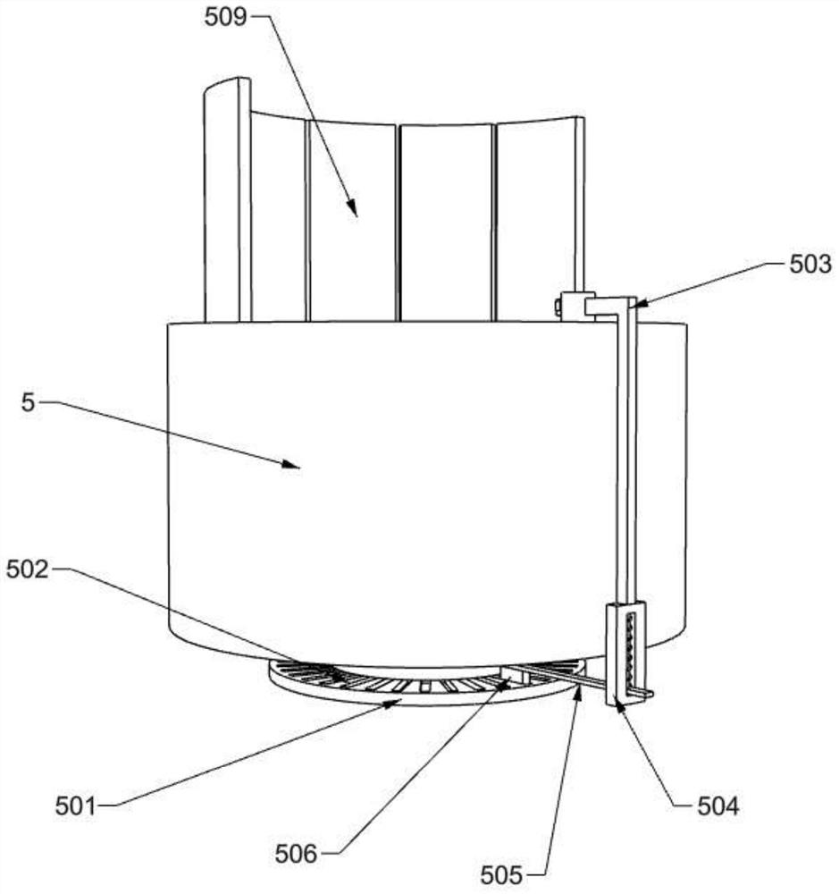
[0034] By moving the connecting plate 505 upward, the limiting block 506 is separated from the limiting groove 502 through the connecting plate 505, so that the installation cylinder 5 can be separated from the ...


PUM


Abstract

The invention discloses a solar intelligent street lamp adopting LoRa technology, which comprises a base, the upper end of the base is fixedly connected with a fixed rod, the outer side of the fixed rod is provided with a clamping mechanism, the clamping mechanism comprises a fixed plate, the two sides of the fixed plate are in threaded connection with adjusting screw rods, the upper ends of the adjusting screw rods are rotatably connected with a moving plate, an illuminating lamp is mounted at the upper end of the moving plate, a mounting cylinder is arranged at the position, located at the upper end of the clamping mechanism, of the outer side of the fixed rod, a bottom plate is fixedly connected to the lower end of the mounting cylinder, and a fixing seat is arranged below the bottom plate. During working, a fixed cylinder is designed, the working height of the illuminating lamp and the solar panel can be adjusted by moving the fixed cylinder up and down, and the invention can be conveniently applied to more working scenes. And a arc-shaped plate is designed, and the arc-shaped plate rotates, so that the solar panel can ascend along with movement of the sun, the solar panel can receive more solar energy, and conversion of energy efficiency is improved.

Description

technical field [0001] The invention relates to a street lamp, in particular to a solar smart street lamp using LoRa technology. Background technique [0002] Smart street lights refer to street lights that realize remote centralized control and management of street lights by applying advanced, efficient, and reliable power line carrier communication technology and wireless GPRS / CDMA communication technology. Smart street lights can automatically adjust brightness according to traffic flow and remote lighting control. , fault active alarm, lighting and cable anti-theft, remote meter reading and other functions can greatly save power resources, improve public lighting management level, and save maintenance costs. [0003] However, the height of the existing smart street lamps cannot be adjusted, and the solar panels are fixed installations, so the solar energy receiving efficiency is limited. Therefore, the present invention provides a solar smart street lamp using LoRa tech...

Claims


Application Information

Patent Timeline
IPC IPC(8): F21S9/03F21V21/36H02S20/32F21W131/103
CPCF21S9/035F21V21/36H02S20/32F21W2131/103Y02E10/50Y02B20/72
Inventor 何小兵何健
Owner 中山市木林森户外照明有限公司
Why Eureka
Try Eureka