Mobile power supply multifunctional platform device
A platform device and multi-functional technology, applied in circuit devices, battery circuit devices, current collectors, etc., can solve problems such as difficulty in using electricity
- Summary
- Abstract
- Description
- Claims
- Application Information
AI Technical Summary
Problems solved by technology
Method used
Image
Examples
Embodiment 1
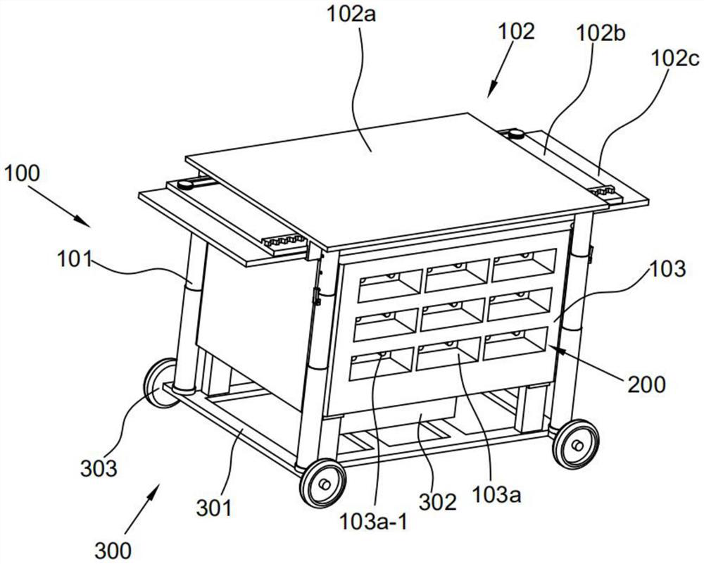
[0025] This embodiment provides a mobile power supply multifunctional platform device, such as figure 1 shown, including,
[0026] The support module 100 includes four vertically arranged support rods 101, the support rods 101 are provided with a panel 102, and the inside of the support rods 101 is provided with an accommodating box 103; the charging module 200 is arranged in the accommodating box 103, including Power supply 201, charging bin 202, and socket 203; and mobile module 300, including a support frame 301 disposed below the storage box 103, a drive unit 302 is disposed on the support frame 301, and wheels 303 are disposed below the support frame 301.
[0027] The support module 100 is the overall support of the device, which plays a supporting role. The overall structure of the device adopts a box type, and the bottom is provided with a mobile module 300, which can be driven by the drive unit 302 to rotate the wheels 303; the output end of the accommodating box 103 i...
Embodiment 2
[0030] This embodiment is different from the previous embodiment in that, as figure 1 , 4 , as shown in 5,
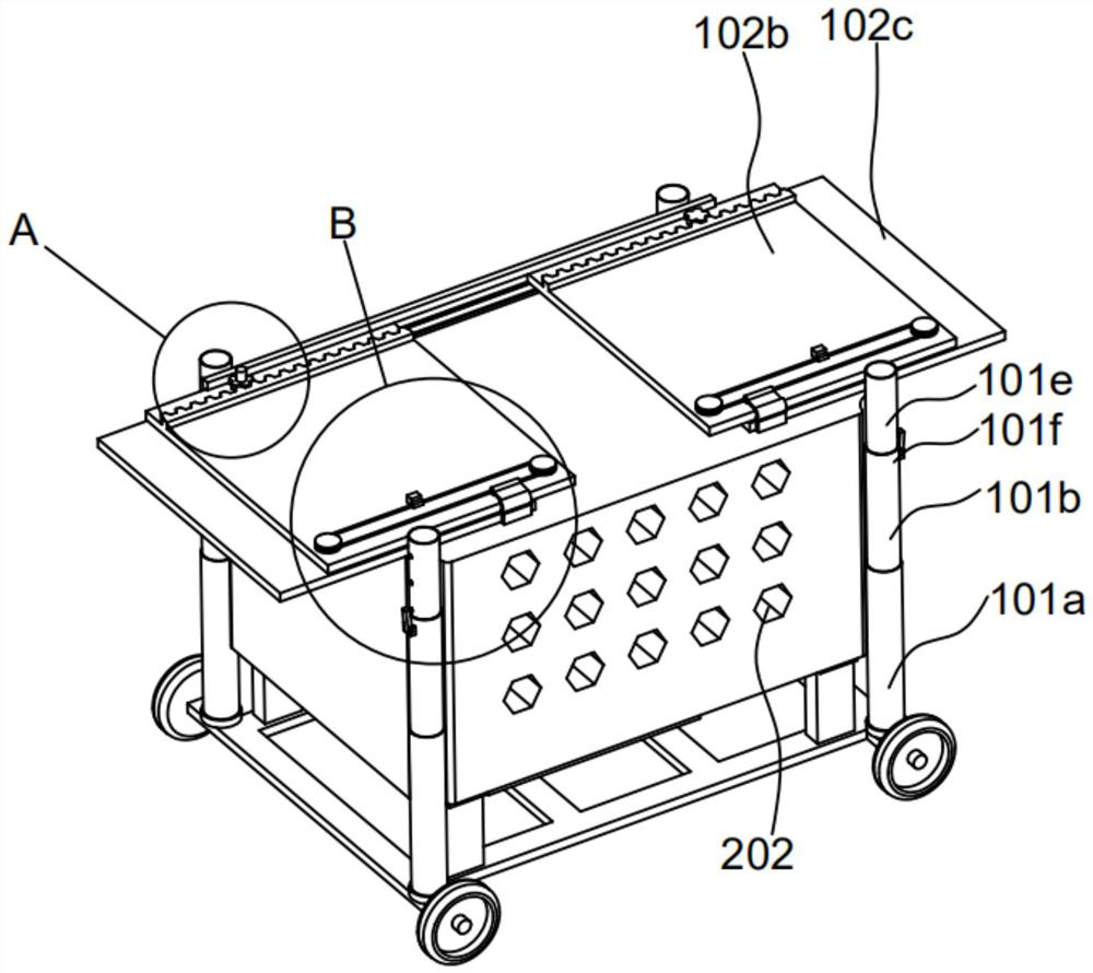
[0031] Wherein the support rod 101 includes the first sleeve 101a arranged at the bottom, the first connecting rod 101b is arranged in the first sleeve 101a, the first rack 101a-1 is symmetrically arranged on the inner wall of the first sleeve 101a, the first A two-way rack 101b-1 is provided at the center of the end of the connecting rod 101b, and a first gear 101c is provided on both sides of the two-way rack 101b-1 to mesh with the first rack 101a-1, and the center of the first gear 101c is provided A first sliding block 101d is connected thereto, and a first sliding rail 101a-2 cooperating with the first sliding block 101d is provided on the inner wall of the first casing 101a.
[0032] Further, the second connecting rod 101e is sheathed inside the first connecting rod 101b, the second sleeve 101f is provided at the joint between the first connecting rod 101b and ...
Embodiment 3
[0035] This embodiment is different from the previous embodiment in that, as Figure 2-4 as shown,
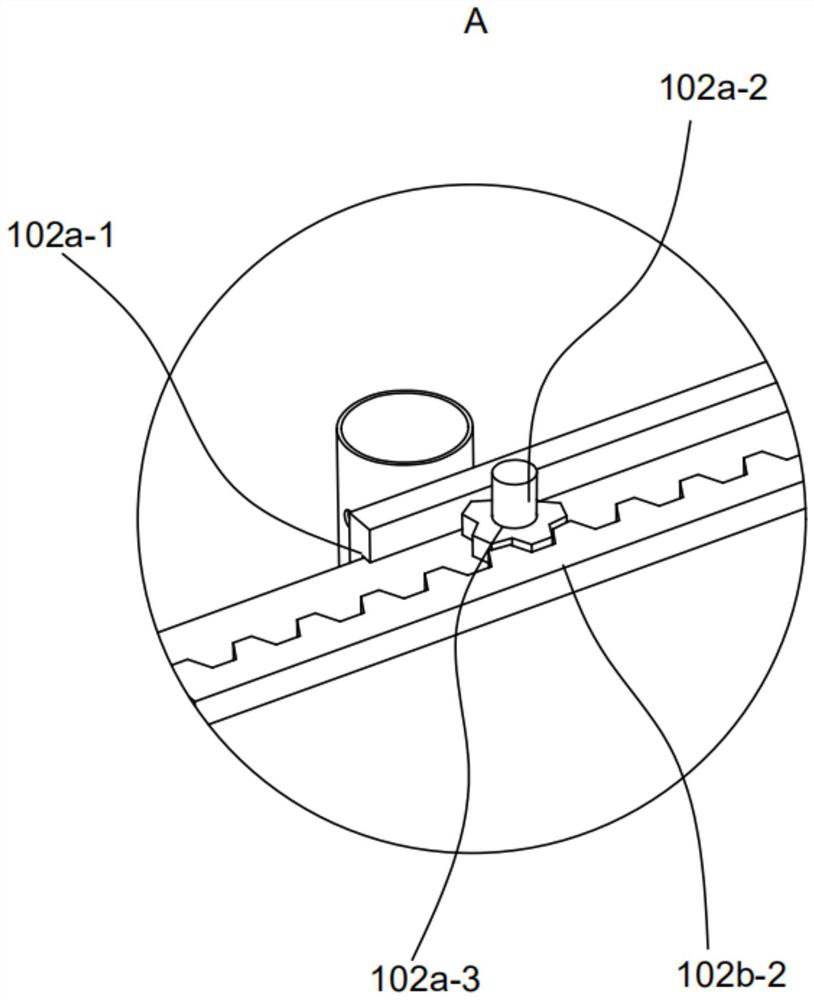
[0036] Wherein the panel 102 comprises a fixed panel 102a, a first panel 102b and a second panel 102c are arranged in parallel below the fixed panel 102a, a second slide rail 102a-1 is arranged behind the fixed panel 102a, the first panel 102b, the second panel 102c and the second panel 102a The two sliding rails 102a-1 are slidingly connected, the first panel 102b and the second sliding rail 102a-1 are provided with rollers in the mating surface, the second panel 102c is slidingly connected to the first panel 102b; the bottom surface of the fixed panel 102a is provided with a first The drive motor 102a-2 is rotatably connected with the second gear 102a-3 on the shaft of the drive motor, and the second rack 102b-2 meshing with the second gear 102a-3 is arranged on the first panel 102b.
[0037] Further, the bottom surface of the fixed panel 102a is also provided with a first sli...
PUM
 Abstract
Description
Claims
Application Information
 - R&D
- Intellectual Property
- Life Sciences
- Materials
- Tech Scout
- Unparalleled Data Quality
- Higher Quality Content
- 60% Fewer Hallucinations
Browse by: Latest US Patents, China's latest patents, Technical Efficacy Thesaurus, Application Domain, Technology Topic, Popular Technical Reports.
© 2025 PatSnap. All rights reserved.Legal|Privacy policy|Modern Slavery Act Transparency Statement|Sitemap|About US| Contact US: help@patsnap.com


