
Grating ruler installation device and method

A technology for installing devices and grating rulers, which is applied in the direction of optical devices, measuring devices, instruments, etc., can solve the problems of grating reading head not being able to read the grating ruler, movement path error, signal loss, etc., to reduce errors and movement paths Consistent, smooth paste results

Pending Publication Date: 2021-11-16
横川机器人(深圳)有限公司 +1
View PDF0 Cites 0 Cited by
  • Summary
  • Abstract
  • Description
  • Claims
  • Application Information

AI Technical Summary

Problems solved by technology

[0004] For the related technologies mentioned above, when the motion track of the object is too long, there is an error between the pasting path of the grating ruler and the movement path of the grating reading head by manually pasting the grating ruler, which makes the grating reading head easy to read. Less than the grating ruler, and thus prone to the defect of signal loss

Method used


Image

  • Grating ruler installation device and method
  • Grating ruler installation device and method
  • Grating ruler installation device and method

Examples


Embodiment 1

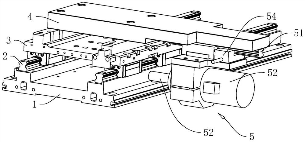
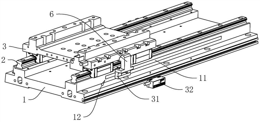
[0045] Embodiment 1, with reference to figure 1 The grating ruler installation device includes a base 1, a guide rail 2, a platform plate 3 and a first connecting frame 4, two guide rails 2 are provided, and the two guide rails 2 are arranged on the base 1 in parallel and at intervals; the platform platform 3 is slidably connected to the base 1 through the guide rail 2. In this embodiment, the object to be detected will be placed on the platform 3 and move along the length extension direction of the guide rail 2 through the platform 3, so as to be detected The purpose of detecting the linear displacement change of the object, in addition, in other embodiments, the guide rail 2 can also be an arc-shaped guide rail, so as to achieve the purpose of changing the angular displacement of the detected object.

[0046] refer to figure 1 and figure 2 , because when the guide rail 2 is straight or arc-shaped, the installation method of the grating ruler 11 is the same, so the follow-...

Embodiment 2

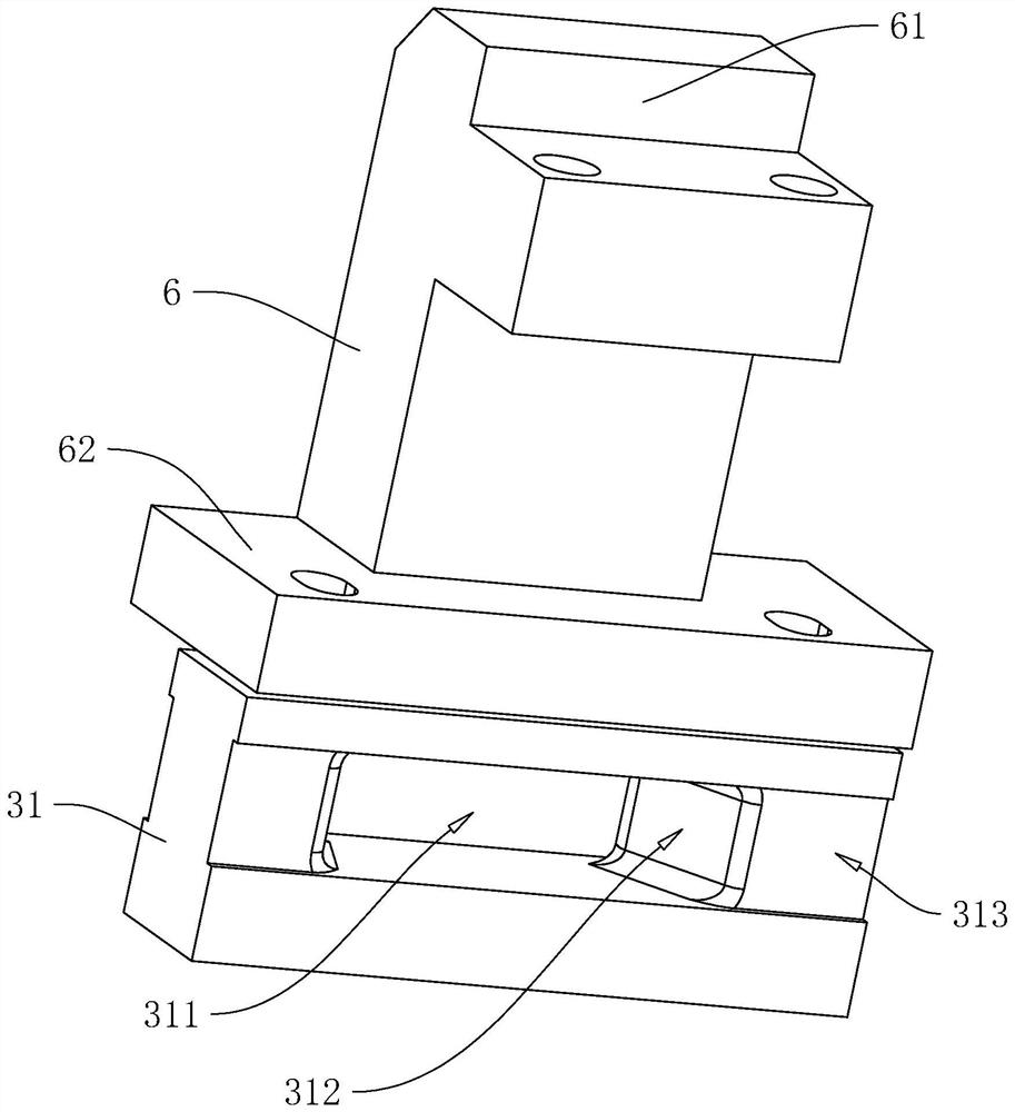
[0055] Embodiment 2, with reference to Figure 4 and Figure 5 The difference from Embodiment 1 is that the two second connecting ends 62 are provided with first connecting holes 621, and the ruler block 31 is provided with a second connecting hole 314 coaxially communicating with the first connecting holes 621, And the first connecting hole 621 and the second connecting hole 314 are provided with a connecting piece 7 that fixes the ruler block 31 and the second connecting frame 6. Specifically, the connecting piece 7 includes two connecting plates 71, a support bar 72, a push The rod 73 and the blocking block 74, the connecting plate 71 is in the shape of a tile, and the connecting plate 71 is passed through the inner circle of the second connecting hole 314. In this embodiment, the first connecting hole 621 is close to the second connecting hole 314 The inner wall of one end is provided with a chute 316 with a T-shaped cross section, and the end of the connecting plate 71 c...


PUM


Abstract

The invention relates to a grating ruler installation device, which comprises a base, a guide rail, a bearing platform plate and a ruler pasting block, and is characterized in that the guide rail is arranged on the base, and the guide rail is used for providing a motion path of a detected object; the bearing platform plate is in sliding connection with the base through the guide rail, and the bearing platform plate is used for detachably connecting the grating reading head and the ruler pasting block; and the surface of the side, where the grating ruler is bonded, of the base is provided with a connection starting position where one end of the grating ruler is pre-bonded, the ruler bonding block is provided with a through hole where the other end of the grating ruler penetrates out, and the surface of the side, close to the base, of the ruler bonding block can abut against the grating ruler. The method has the effect that the pasting path of the grating ruler and the motion path of the grating read head are not easy to have errors.

Description

technical field [0001] The present application relates to the field of installation equipment, in particular to a grating scale installation device and method. Background technique [0002] The grating ruler, also known as the grating ruler displacement sensor, is a measurement feedback device that uses the optical principle of the grating. The grating ruler is often used in the closed-loop servo system of the CNC machine tool, and can be used for the detection of linear displacement or angular displacement. The output signal of ruler measurement is a digital pulse, so it has the characteristics of large detection range, high detection accuracy and fast response speed. [0003] In related technologies, when it is necessary to detect linear displacement or angular displacement of an object, the object will be installed on a bracket first, and the bracket is slidably connected to a base, and the sliding track of the bracket is consistent with the predetermined movement track o...

Claims


Application Information

Patent Timeline
Patent Type & Authority Applications(China)
IPC IPC(8): G01B11/02G01B11/26
CPCG01B11/02G01B11/26
Inventor 王书华杨小军王建云刘步军
Owner 横川机器人(深圳)有限公司
Learn More