
Mold replacing device of injection mold

A technology for injection molds and molds, which is applied in the field of mold changing devices for injection molds. It can solve the problems of low mold loading efficiency, easy installation errors, and long labor time, and achieves the effects of convenient operation, less error, and reduced labor intensity.

Inactive Publication Date: 2017-01-04
TIANJIN LIANJIE PLASTIC PROD
View PDF0 Cites 0 Cited by
  • Summary
  • Abstract
  • Description
  • Claims
  • Application Information

AI Technical Summary

Problems solved by technology

[0002] In the injection molding process, it is necessary to assemble and replace the molds used for product molding. With the rapid development of the automobile industry, quick mold change has become the core competitiveness of injection molding factories. The method is the traditional manual operation of bolts and pressing plates. This method will not only be affected by the operator's experience and physical strength, but also has long labor time, low mold loading efficiency, and easy installation errors.

Method used


Image

  • Mold replacing device of injection mold
  • Mold replacing device of injection mold
  • Mold replacing device of injection mold

Examples


Embodiment 1

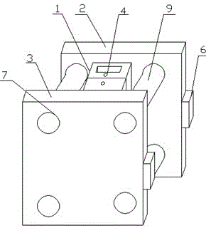
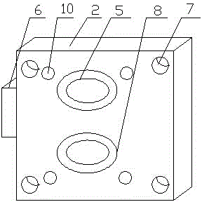
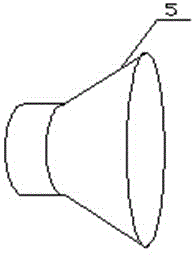
[0011] The invention provides a mold changing device for an injection mold, comprising a mold 1, a front mold backing plate 2, a rear mold backing plate 3, a suspension ring 4, a vacuum sucker 5, a vacuum pump 6, a through hole 7, an electromagnetic heating pipeline 8, bolts 9, Mold correction device 10, the top of the mold 1 is provided with a suspension ring 4, the front mold backing plate 2 and the rear mold backing plate 3 are provided with a vacuum chuck 5, a through hole 7, an electromagnetic heating pipeline 8, an infrared sensor 9 and Die correction device 10, a vacuum pump 6 is installed on one side of the front mold backing plate 2 and the back mold backing plate 3, the back of the mold 1 is connected with the vacuum chuck 5, the vacuum chuck 5 is connected with the vacuum pump 6, and the vacuum An electromagnetic heating pipeline 8 is arranged on the outside of the suction cup 5 , and the bolt 9 connects the front mold backing plate 2 and the back mold backing plate ...

Embodiment 2

[0013] When disassembling the old mold, the bolt 9 passing through the through hole 7 is disassembled, the front mold backing plate 2 and the back mold backing plate 3 can be separated, the vacuum pump 6 is turned off, and the abrasive tool 1 is connected to the front mold backing plate 2 and the back mold The backing plate 3 is separated, and the old mold 1 can be hoisted by the crane through the suspension ring 4.

[0014] When installing a new mold, the crane hangs the new mold 1 between the front mold backing plate 2 and the rear mold backing plate 3 through the lifting ring 4, starts the electromagnetic heating pipeline 8 to preheat the mold 1 before processing, and the mold corrector 10 Correct the deviation of the mold 1 with an error in the placement position, start the vacuum pump 6, and the vacuum suction cup 5 will work to suck the mold 1 tightly on the surface of the front mold backing plate 2 and the rear mold backing plate 3. After that, the operator puts the bolt...


PUM


Abstract

The invention provides a mold replacing device of an injection mold. The mold replacing device comprises the mold, lifting rings and the like. The mold replacing device is characterized by further comprising vacuum suction cups, vacuum pumps, electromagnetic heating pipelines, infrared inductors and mold deviation correctors; the lifting rings are arranged on the top of the mold, a front mold cushion plate and a rear mold cushion plate are provided with the vacuum suction cups, through holes, the electromagnetic heating pipelines, the infrared inductors and the mold deviation correctors correspondingly; the vacuum pumps are arranged on one side of the front mold cushion plate and one side of the rear mold cushion plate; and the back face of the mold is connected with the vacuum suction cups. The vacuum suction cups are additionally arranged, damage to workpieces is avoided in the work process, and errors are not likely to happen. The mold deviation correctors are arranged, and the situations of falling and operator bruising caused by position deviation in the carrying process are avoided. The electromagnetic heating pipelines are arranged, so that the preheating time needed after the mold is replaced and before a new mold works is shortened. The mold replacing device is simple in structure, convenient to operate and capable of effectively shortening the time needed for production and improving the production efficiency.

Description

technical field [0001] The invention relates to the technical field of injection molds, in particular to a mold changing device for injection molds. Background technique [0002] In the injection molding process, it is necessary to assemble and replace the molds used for product molding. With the rapid development of the automobile industry, quick mold change has become the core competitiveness of injection molding factories. The method is the traditional manual operation of bolts and pressing plates. This method will not only be affected by the operator's experience and physical strength, but also has long labor time, low mold loading efficiency, and easy installation errors. Contents of the invention [0003] According to the above technical problems, the present invention provides a mold changing device for an injection mold, which includes a mold, a front mold backing plate, a rear mold backing plate, a lifting ring, and a through hole, and is characterized in that it ...

Claims


Application Information

Patent Timeline
IPC IPC(8): B29C45/26B29C33/30
CPCB29C45/2673B29C33/30
Inventor 徐宏伟
Owner TIANJIN LIANJIE PLASTIC PROD
Learn More