
Method and structure for improving performance and storage density in a data storage device

a data storage device and performance improvement technology, applied in the field of data storage devices, to achieve the effect of improving data storage density, improving data storage, and reducing the average track-to-track spacing

Inactive Publication Date: 2015-05-21
WESTERN DIGITAL TECH INC
View PDF9 Cites 0 Cited by
  • Summary
  • Abstract
  • Description
  • Claims
  • Application Information

AI Technical Summary

Benefits of technology

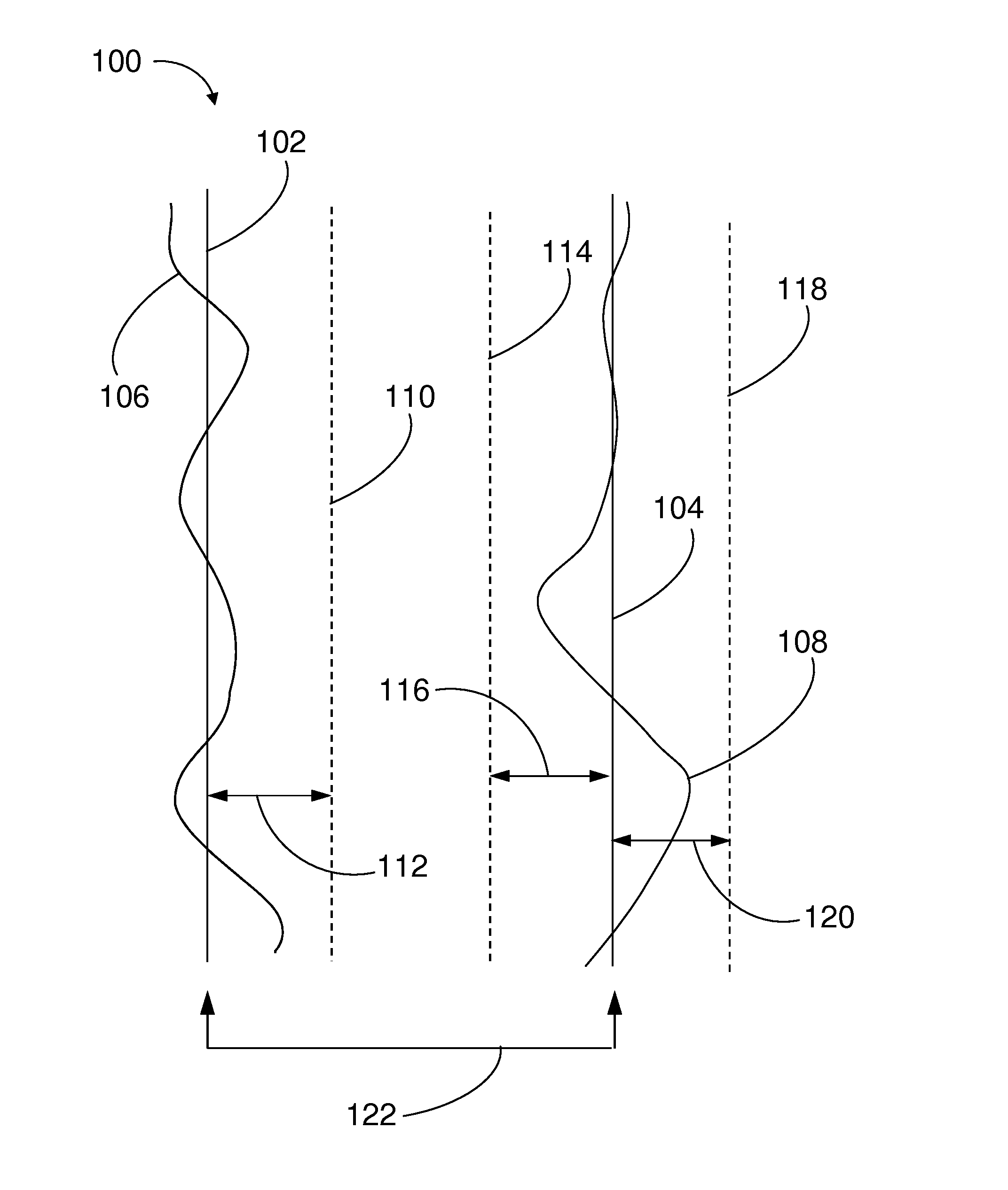
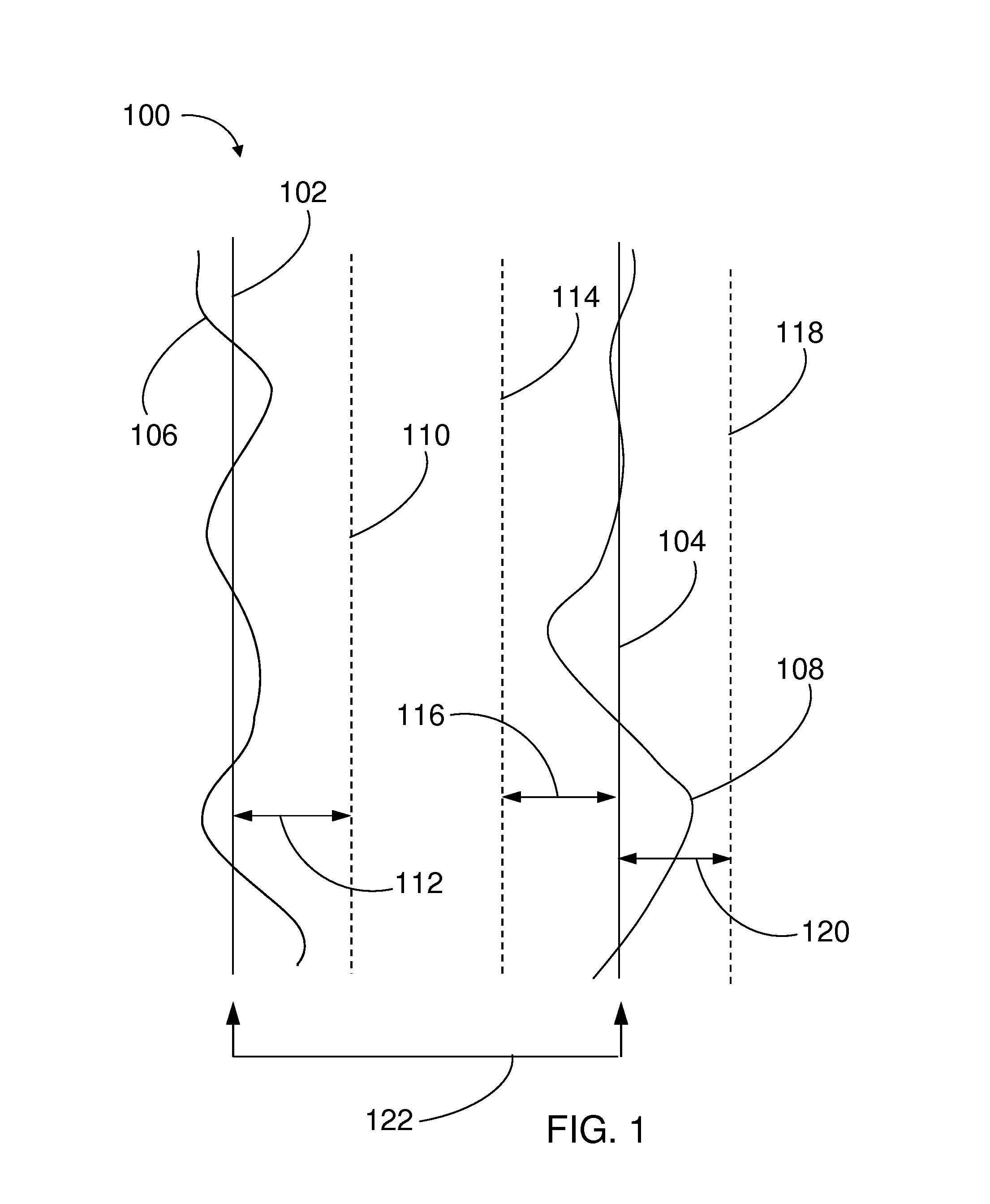
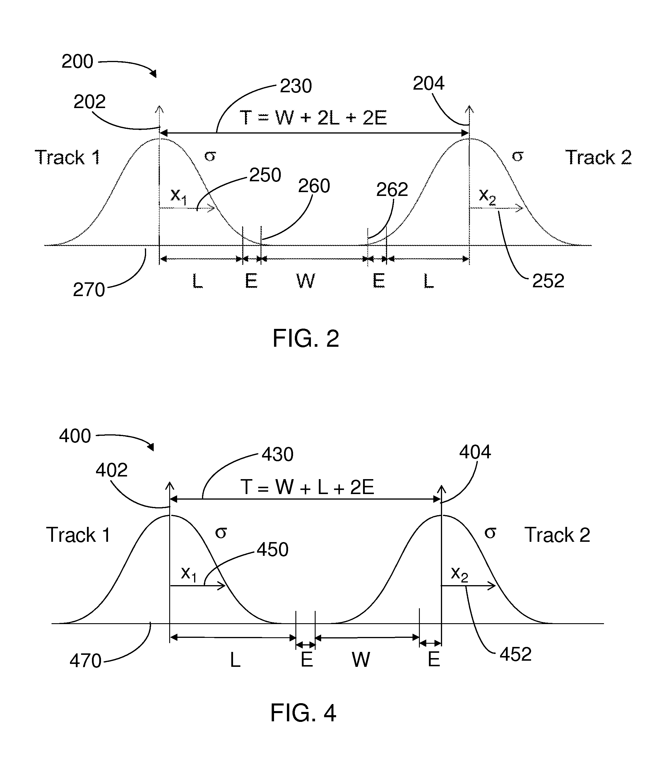
The present invention provides a method for improving data storage in hard disk drives or other data storage devices employing a rotating medium. The method uses a feed-forward method that takes into account the actual location of a neighboring data track to reduce the average track-to-track spacing, resulting in improved data storage density and reduced hard error and write inhibit hits to the writing performance. The method also addresses the use of virtual tracks to improve storage densities and lower hard error and write inhibit events. Additionally, the method improves operational vibration environments through the feed forward write inhibit method, with trade-offs between performance and storage density.

Problems solved by technology

Operational shock may result in large PES values over short time periods during which it may be preferred to prevent write or read events, thereby avoiding writing outside the desired track regions, and possibly even “head crashes”.

Method used


Image

  • Method and structure for improving performance and storage density in a data storage device
  • Method and structure for improving performance and storage density in a data storage device
  • Method and structure for improving performance and storage density in a data storage device

Examples


first embodiment

[0040]In the present invention, the FFWI Factor α may have a different value for different physical zones on the storage medium. As discussed above, for E-regions, the trade-off is between performance and HE rates. This is applicable to any cache or temporary storage region where data is first written, typically as fast as possible to avoid delaying the host device. Tuning of the optimal α value may easily be performed on-line. For I-regions, the trade-off is between performance and higher TPI (denser storage). This is applicable to any region where data is finally stored and efficiency of storage is more useful (maximize TPI). Although on-line adjustment is possible, off-line tuning may be most practical.

second embodiment

[0041]In the present invention, in an operational vibration (“op-vib”) environment, a trade-off between performance and HE rates (similar to that used in writing E-regions) is applicable. As PES prediction rates are affected by op-vib, the FFWI Factor α may be adjusted to lower HE rates, or at least maintain HE rates in the face of increased vibration-induced head motions.

Data Storage Device Operation for E-Regions in Operational Vibration Conditions

[0042]FIG. 7 is a graph 700 similar to graph 500 in FIG. 5, except under large speaker vibration environment in a laptop computer while playing loud music. As a result of this op-vib environment, the ranges for the FFWI Factor α are shifted to lower values, typically over the approximate range 1.2≦α≦1.56 (compared with the range 1.37≦α≦1.66 in the absence of loud noise). This shift to lower α values compensates for the increased head motion induced by the op-vib environment since lower α values cause the FFWI method of the present invent...


PUM

PropertyMeasurementUnit
rotationaaaaaaaaaa
track widthsaaaaaaaaaa

Abstract

A data storage device with improved data storage densities, coupled with lower hard error and write-inhibit events is described. A feed-forward write inhibit (FFWI) method enables data tracks to be written more densely. Alternatively, the FFWI method may reduce the hard error and write inhibit events to improve data storage performance. A concept of virtual tracks enables the FFWI method to be applied to the writing of circular data tracks with non-circular servo tracks, or to the writing of non-circular data tracks with PES data from circular servo tracks—in both cases, improvements to performance and / or storage densities are enabled. The FFWI method may also be applied to the case of both non-circular servo and data tracks.

Description

[0001]This application is a Divisional of U.S. Utility patent application Ser. No. 13 / 593,991, filed Aug. 24, 2012, which is incorporated herein by reference in its entirety.TECHNICAL FIELD OF THE INVENTION[0002]The present invention relates to data storage devices, and in particular to data storage devices with various data storage regions having different optimization requirements, such as write inhibit rates, hard error rates, and data storage densities.BACKGROUND OF THE INVENTION[0003]The present invention relates to data storage devices employing rotating data storage media. As described in U.S. Pat. No. 7,394,607, the location of the write head relative to the desired location of the track is the position error signal (PES), which is generated during passage of the read head over a “servo burst region” contained within a servo zone (also termed a “servo spoke”). Typical disks may have more than 250 approximately radial servo zones, thereby providing PES values roughly every 1°...

Claims


Application Information

Patent Timeline
Patent Type & Authority Applications(United States)
IPC IPC(8): G11B20/12
CPCG11B2020/1238G11B20/1252G11B5/09G11B5/59694G11B5/56G11B5/5543
Inventor DHANDA, ABHISHEKHIRANO, TOSHIKISEMBA, TETSUO
Owner WESTERN DIGITAL TECH INC
Learn More