
Patsnap Eureka
For R&D, Patsnap Eureka makes reading and utilizing patents & technical documents easy.
Patsnap Eureka AIR
Designed for self-driven R&D workflows. Generate viable solutions, solve complex R&D challenges, empower your innovation with AI.

Patsnap Eureka Materials
Designed for material experts only. Revolutionize your material R&D, from search, analyze, to developing new materials.

TechResearch
Generate reliable direction feasibility study reports for your R&D in just a few steps.

TechSeek
Discover and master advanced knowledge NOW. Basics, ideas, possibilities, all at once.

TechMind
As an expert in R&D Theories, TechMind can generates customized viable solutions instantly.

TechRisk
Analyze your overall solution with one click, know your potential R&D risks in advance.

TechMonitor
Get weekly tech updates, stay abreast of the latest tech innovations and key insights.
Optical imaging system
An optical imaging system and optical axis technology, applied in optics, optical components, instruments, etc., can solve the problems of being unable to meet the needs of shooting close-up shots and zooming in on the subject, and achieve the effect of maintaining the characteristics of the telephoto lens and good imaging quality
- Summary
- Abstract
- Description
- Claims
- Application Information
AI Technical Summary
Problems solved by technology
Method used
Image

Examples
specific Embodiment 1
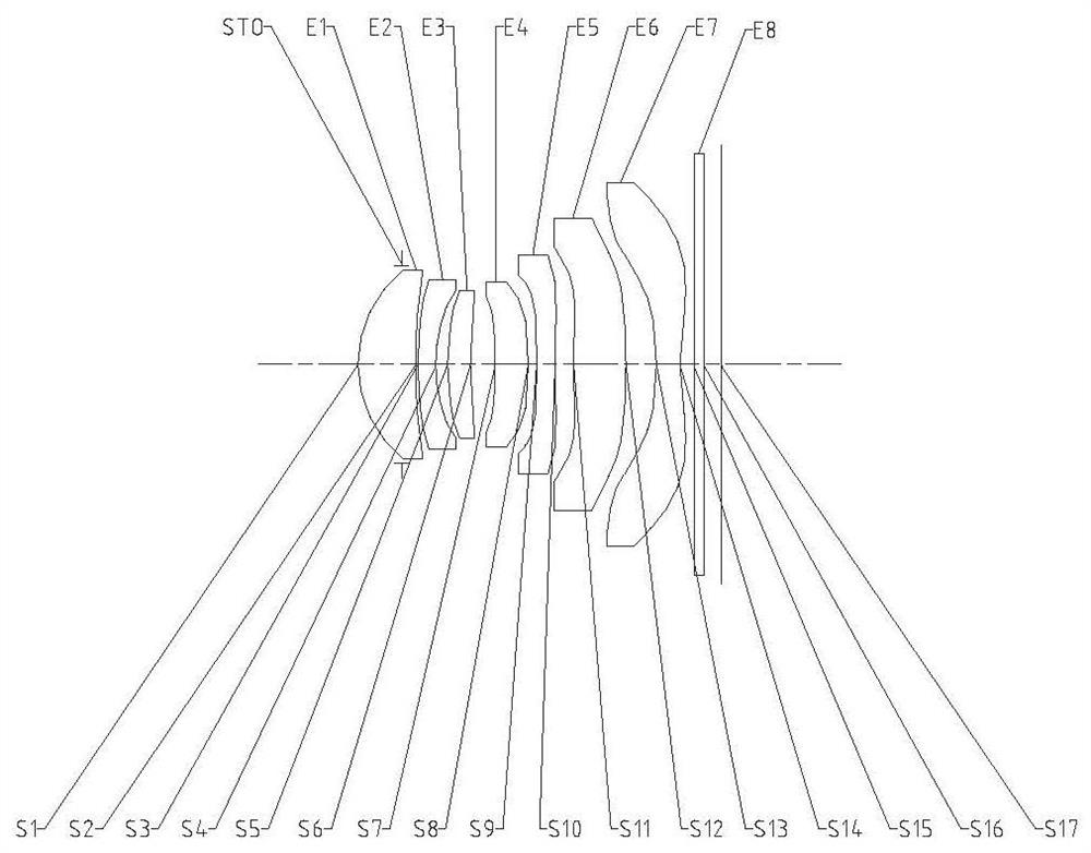
[0102] figure 1 It is a schematic diagram of the structure of the lens group in Embodiment 1 of the optical imaging system of the present invention. The optical imaging system includes in sequence from the object side to the image side along the optical axis: a diaphragm STO, a first lens E1, a second lens E2, a third lens E3, The fourth lens E4, the fifth lens E5, the sixth lens E6, the seventh lens E7, the filter E8 and the imaging surface S17.
[0103] The first lens E1 has positive refractive power, its object side S1 is convex, and its image side S2 is concave. The second lens E2 has negative refractive power, its object side S3 is convex, and its image side S4 is concave. The third lens E3 has positive refractive power, its object side S5 is convex, and its image side S6 is concave. The fourth lens E4 has positive refractive power, its object side S7 is concave, and its image side S8 is convex. The fifth lens E5 has negative refractive power, its object side S9 is con...
Embodiment 1
[0111] The optical imaging system in embodiment 1 satisfies:
[0112] TTL / f=1.17; wherein, TTL is the on-axis distance from the object side of the first lens to the imaging surface, and f is the effective focal length of the optical imaging system.
[0113] f5 / f=-7.47; wherein, f is the effective focal length of the optical imaging system, and f5 is the effective focal length of the fifth lens.
[0114] R2 / R1=8.01; wherein, R1 is the radius of curvature of the object side of the first lens, and R2 is the radius of curvature of the image side of the first lens.
[0115] f6 / f7=-2.27; wherein, f6 is the effective focal length of the sixth lens, and f7 is the effective focal length of the seventh lens.
[0116] (R9+R10) / (R9-R10)=2.39; wherein, R9 is the radius of curvature of the object side of the fifth lens, and R10 is the radius of curvature of the image side of the fifth lens.
[0117] R12 / R13=1.38; wherein, R11 is the radius of curvature of the object side of the sixth lens...
specific Embodiment 2
[0130] image 3 It is a schematic diagram of the structure of the lens group in Embodiment 2 of the optical imaging system of the present invention. The optical imaging system includes in sequence from the object side to the image side along the optical axis: a diaphragm STO, a first lens E1, a second lens E2, a third lens E3, The fourth lens E4, the fifth lens E5, the sixth lens E6, the seventh lens E7, the filter E8 and the imaging surface S17.
[0131] The first lens E1 has positive refractive power, its object side S1 is convex, and its image side S2 is concave. The second lens E2 has negative refractive power, its object side S3 is convex, and its image side S4 is concave. The third lens E3 has positive refractive power, its object side S5 is convex, and its image side S6 is concave. The fourth lens E4 has positive refractive power, its object side S7 is concave, and its image side S8 is convex. The fifth lens E5 has negative refractive power, its object side S9 is con...
PUM
 Abstract
Description
Claims
Application Information
 - R&D Engineer
- R&D Manager
- IP Professional
- Industry Leading Data Capabilities
- Powerful AI technology
- Patent DNA Extraction
Browse by: Latest US Patents, China's latest patents, Technical Efficacy Thesaurus, Application Domain, Technology Topic, Popular Technical Reports.
© 2024 PatSnap. All rights reserved.Legal|Privacy policy|Modern Slavery Act Transparency Statement|Sitemap|About US| Contact US: help@patsnap.com