Zoom lens and imaging apparatus

a zoom lens and imaging apparatus technology, applied in the field of zoom lenses and imaging apparatuses, can solve the problems of less likely to be acceptable in the market, easy choice etc., and achieve the effects of increasing the size of the apparatus, high quality, and high performan

Active Publication Date: 2015-10-22
FUJIFILM CORP
View PDF0 Cites 9 Cited by
  • Summary
  • Abstract
  • Description
  • Claims
  • Application Information

AI Technical Summary

Benefits of technology

[0027]The sign of the refractive power and the shape of a lens surface are considered in a paraxial region when an aspheric surface is included. According to the zoom lens of the present invention, the zoom lens consists of six lens groups, and the arrangement of refractive power of the lens groups is appropriately set. Further, lens groups that are fixed during magnification change and a change in distance between the lens groups during magnification change are appropriately set. Therefore, a small F-number and higher performance are achievable while the compactness is maintained.
[0028]According to the imaging apparatus of the present invention, the imaging apparatus includes the zoom lens of the present invention. Therefore, high quality images are obtainable without increasing the size of the apparatus, and excellent imaging is possible even under low illumination conditions.

Problems solved by technology

Therefore, an easy choice of increasing the size of the apparatus would be less likely to be acceptable in the market, and the apparatus needs to maintain its compactness.

Method used


Image

  • Zoom lens and imaging apparatus
  • Zoom lens and imaging apparatus
  • Zoom lens and imaging apparatus

Examples


example 1

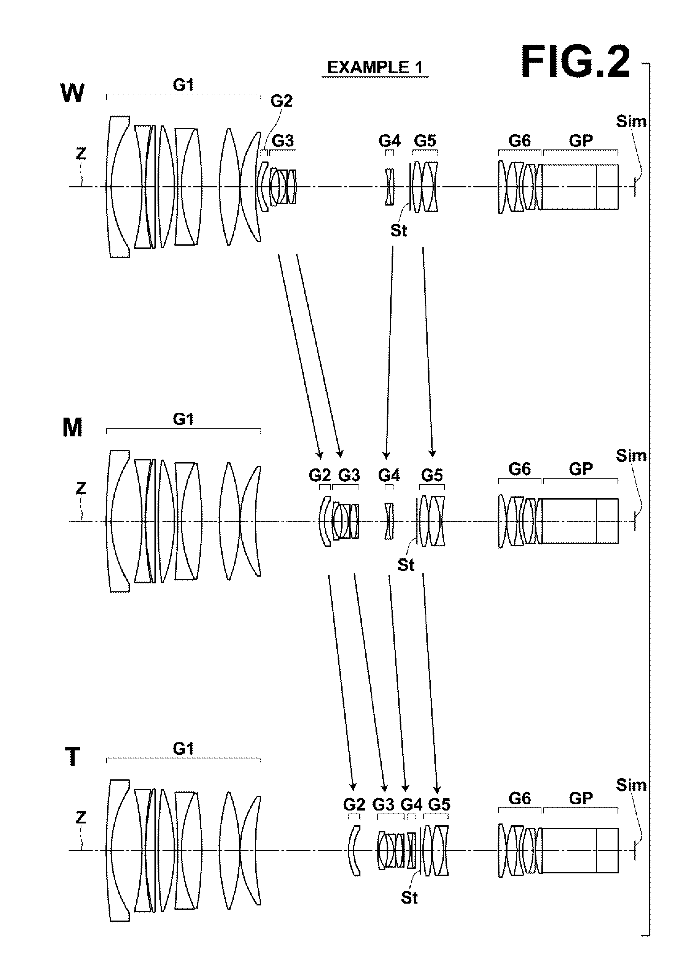
[0087]FIG. 2 is a sectional diagram illustrating the configuration of a zoom lens in Example 1. In FIG. 2, a top row, a middle row and a bottom row to which signs W, M and T are attached to the left side of the diagram, respectively, illustrate the arrangement and configuration of each lens group at the wide angle end, a middle focal length state, and the telephoto end, respectively. Further, arrows illustrated between the top row and the middle row and arrows illustrated between the middle row and the bottom row schematically illustrate a path of movement of each lens group that moves during magnification change.

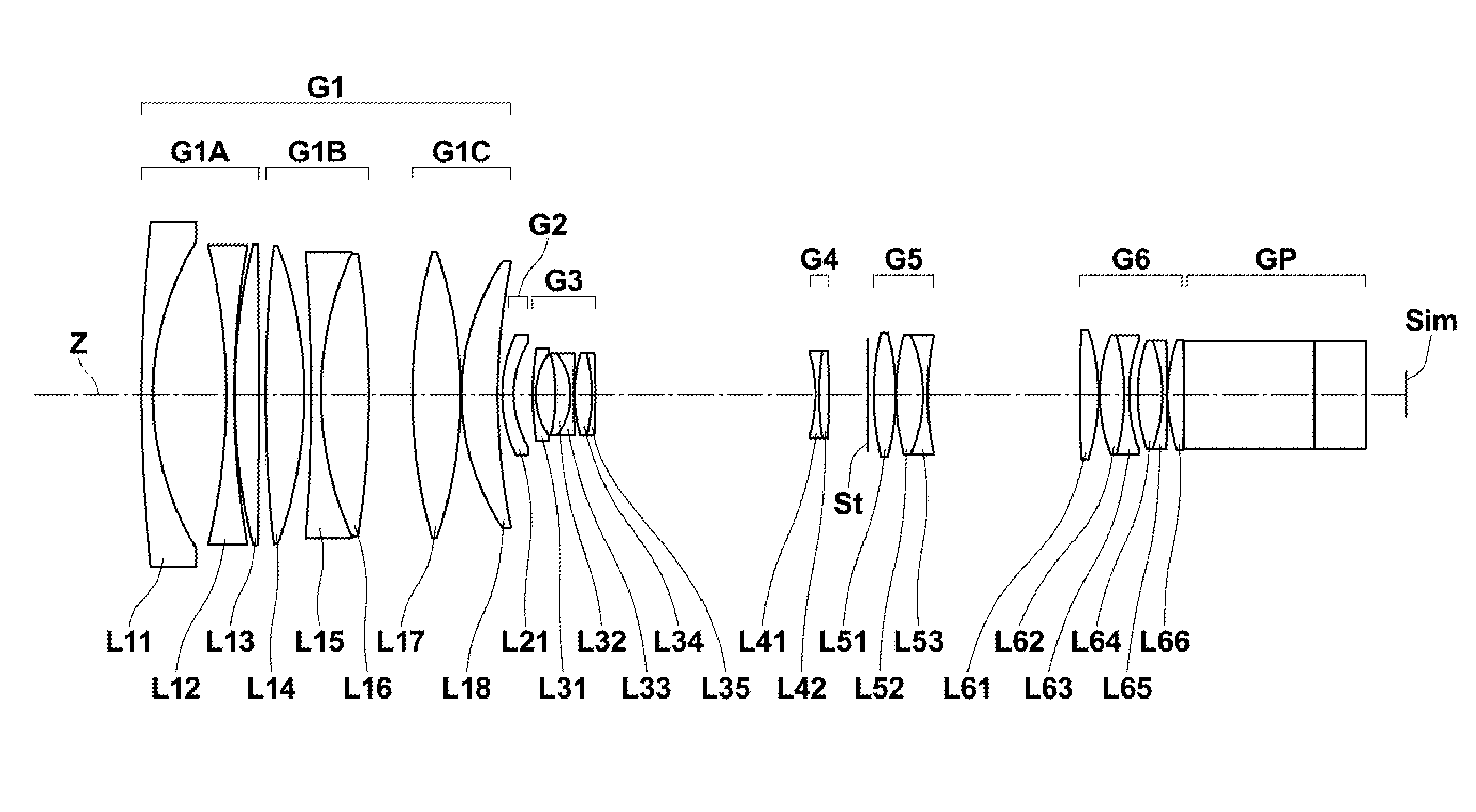
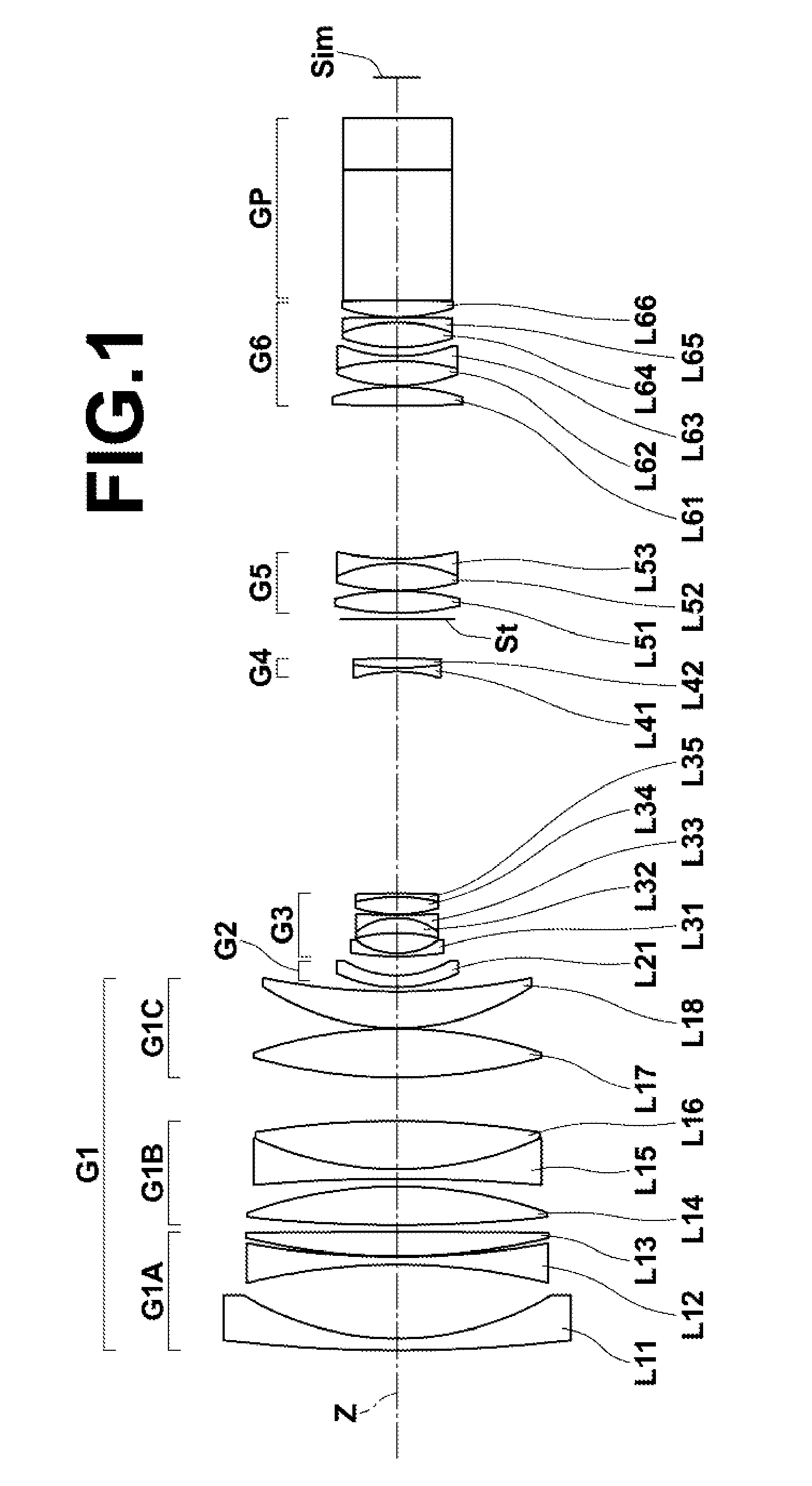
[0088]As the group configuration of the zoom lens in Example 1, the zoom lens consists of six lens groups of, in order from the object side, first lens group G1 having positive refractive power, second lens group G2 having negative refractive power, third lens group G3 having negative refractive power, fourth lens group G4 having negative refractive power, fifth lens group ...

example 2

[0104]FIG. 3 is a diagram illustrating the lens configuration of a zoom lens in Example 2. The group configuration, the schematic configuration of lenses in each lens group and the position of aperture stop St in the zoom lens of Example 2 are similar to those of Example 1, which have been described already. Table 4, Table 5 and Table 6 show the basic lens data, specification and variable surface distances, and aspherical coefficients of the zoom lens in Example 2, respectively. FIG. 7, Sections A through L are aberration diagrams of the zoom lens in Example 2.

TABLE 4SiRiDiNdjνdj*1363.39743.011.8160046.62271.557718.903−147.90502.001.8830040.764219.19430.155159.54536.061.8466123.786−2289.63522.007342.83939.711.4874970.238−106.59161.859−391.39772.301.6388634.371083.478112.291.4970081.5411−214.728711.0312127.880912.391.4338795.2013−106.50220.15*1455.92669.251.5952267.7415159.7509DD[15]*1632.64703.001.8830040.761724.4041DD[17]1871.68820.801.8980034.001917.08075.0620−39.82723.821.8080922...

example 3

[0105]FIG. 4 is a diagram illustrating the lens configuration of a zoom lens in Example 3. The group configuration, the schematic configuration of lenses in each lens group and the position of aperture stop St in the zoom lens of Example 3 are similar to those of Example 1, which have been described already. Table 7, Table 8 and Table 9 show the basic lens data, specification and variable surface distances, and aspherical coefficients of the zoom lens in Example 3, respectively. FIG. 8, Sections A through L are aberration diagrams of the zoom lens in Example 3.

TABLE 7SiRiDiNdjνdj*1381.11253.001.8040046.58271.503618.213−149.52732.041.8830040.764221.22260.155177.67225.891.8466123.786−1370.43042.007267.491210.251.4874970.238−110.03031.959−390.43202.301.6200436.261083.889812.671.4387594.9311−188.761211.1312119.623212.881.4338795.2013−101.23660.33*1456.22528.701.5952267.7415144.4949DD[15]*1633.17893.001.8348142.731725.3077DD[17]1869.52820.801.8980034.001917.08505.1920−38.90843.721.808092...


PUM


Abstract

A zoom lens consists of, in order from the object side, a positive first lens group, a negative second lens group, a negative third lens group, a negative fourth lens group, a positive fifth lens group, and a positive sixth lens group. The first lens group and the sixth lens group are fixed with respect to an image plane, and a distance between the first lens group and the second lens group increases, a distance between the second lens group and the third lens group changes, and a distance between the third lens group and the fourth lens group changes, and a distance between the fourth lens group and the fifth lens group changes, and a distance between the fifth lens group and the sixth lens group changes during magnification change from a wide angle end to a telephoto end.

Description

CROSS-REFERENCE TO RELATED APPLICATIONS[0001]This application is a Continuation of PCT International Application No. PCT / JP2013 / 007643 filed on Dec. 26, 2013, which claims priority under 35 U.S.C §119(a) to Japanese Patent Application No. 2013-008848 filed on Jan. 22, 2013. Each of the above applications is hereby expressly incorporated by reference, in its entirety, into the present application.BACKGROUND OF THE INVENTION[0002]1. Field of the Invention[0003]The present invention relates to a zoom lens and an imaging apparatus. In particular, the present invention relates to a zoom lens appropriate to be mounted on a digital camera, a camera for surveillance, a camera for film making, a camera for broadcasting and the like and an imaging apparatus including this zoom lens.[0004]2. Description of the Related Art[0005]Conventionally, as a zoom lens, and particularly as a zoom lens appropriate for a camera for film making and a camera for broadcasting, a zoom lens consisting of four le...

Claims


Application Information

Patent Timeline
Patent Type & Authority Applications(United States)
IPC IPC(8): G02B15/14
CPCG02B15/14G02B13/18G02B15/17G02B15/20G02B27/1013G02B15/145117G02B15/1461
Inventor KOMATSU, DAIKICHO, MICHIO
Owner FUJIFILM CORP
Why Eureka
Try Eureka