

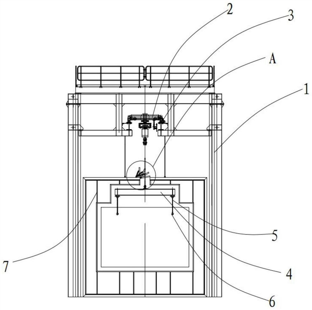
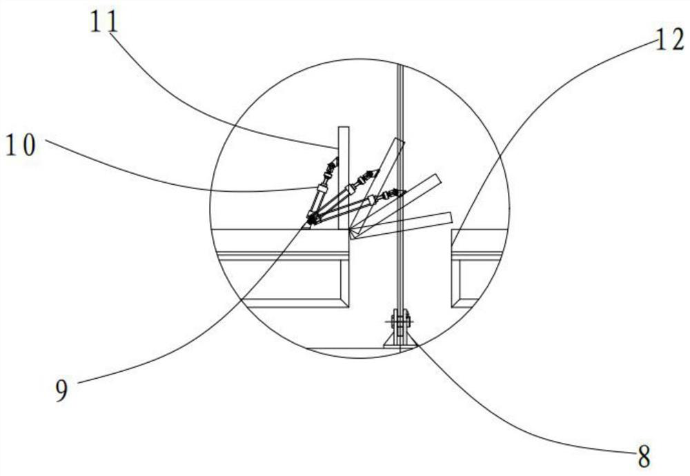
Novel drying chamber body sealing structure
A technology of sealing structure and drying chamber, which is applied to the device for coating liquid on the surface, pretreatment surface, coating, etc., can solve the problems of thermal aging and peeling off of rubber sheet, increasing energy consumption, and affecting the quality of paint on the surface of the workpiece, etc. Reliable operation, good sealing effect, easy installation and maintenance
- Summary
- Abstract
- Description
- Claims
- Application Information
AI Technical Summary
Problems solved by technology
Method used
Image

Examples
Embodiment Construction
[0016] The technical solutions in the embodiments of the present invention will be clearly and completely described below in conjunction with the accompanying drawings in the embodiments of the present invention. Obviously, the described embodiments are only some of the embodiments of the present invention, not all of them. Based on The embodiments of the present invention and all other embodiments obtained by persons of ordinary skill in the art without making creative efforts belong to the protection scope of the present invention.
[0017] In the description of the present invention, it should be understood that the orientations or positional relationships indicated by "front", "rear", "left", "right", "upper" and "lower" in terms are based on those shown in the accompanying drawings. Orientation or positional relationship is only for the convenience of describing the present invention and simplifying the description, and does not indicate or imply that the device or element...
PUM
 Abstract
Description
Claims
Application Information