A stacking device for a plate production line

A production line and plate technology, which is applied in the direction of object stacking, transportation and packaging, roller tables, etc., can solve the problems of low stacking efficiency, inability to fix and limit, and plate damage, etc., to achieve enhanced stacking efficiency, simple stacking, and guaranteed The effect of stability

Active Publication Date: 2022-04-15
徐州苏力德木业有限公司
View PDF7 Cites 0 Cited by
  • Summary
  • Abstract
  • Description
  • Claims
  • Application Information

AI Technical Summary

Problems solved by technology

[0004] In order to solve the above technical problems, the present invention provides a stacking device for a plate production line to solve the problem that the existing stacking methods basically use manual movement of the plates, and the stacking efficiency is low; and the existing plate stacking device cannot effectively Fix and limit the boards according to their size, causing the boards to be damaged to a certain extent when stacked

Method used


Image

  • A stacking device for a plate production line
  • A stacking device for a plate production line
  • A stacking device for a plate production line

Examples


Embodiment 1

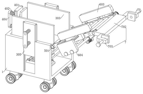
[0033] Embodiment one: as attached figure 1To attach Figure 8 As shown: the present invention provides a stacking device for a plate production line, including a device main body 1; the device main body 1 includes: a fixed plate 101, a lifting rod A102, a lifting rod B103, a connecting plate 104 and a connecting rod 105, and the fixing plate 101 is fixedly arranged At the bottom of the inner side of the device main body 1; the lifting rod A102 is rotatably set on the top of the fixed plate 101; the bottom of the lifting rod B103 is rotatably set with a shaft, and the shaft is slidably set on the top of the fixed plate 101; the lifting rod B103 and the lifting rod A102 are rotatably connected , and a hydraulic rod is set between the shaft at the bottom of the lifting rod B103 and the fixed plate 101; the connecting plate 104 is rotatably set on the top of the lifting rod B103; the connecting rod 105 is rotatably set on the top of the lifting rod A102, and the connecting rod 10...

Embodiment 2

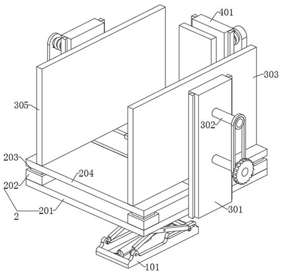
[0038] Embodiment two: as attached figure 2 As shown, on the basis of Embodiment 1, other structures remain unchanged. In this embodiment, the load-bearing mechanism 2 includes: a load-bearing plate 201, a load-bearing column 202, a connecting column 203 and a bottom plate 204, and the load-bearing plate 201 is fixedly arranged on the top of the connecting plate 104. The load-bearing column 202 is fixedly arranged on the top of the load-bearing plate 201, and the interior of the load-bearing column 202 is set as a hollow structure; the number of the load-bearing column 202 is set to four groups; Spring parts are arranged inside; the bottom plate 204 is fixedly arranged on the top of the connecting column 203; by setting the load-bearing column 202, the connecting column 203 and the spring parts, the effect of buffering the board is realized, and the damage to the board is prevented when the board is lowered role.

Embodiment 3

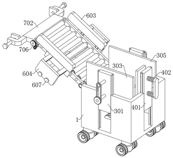
[0039] Embodiment three: as attached Figure 11 As shown, on the basis of Embodiment 1, other structures remain unchanged. In this embodiment, the fixing frame 301 is fixedly arranged on both sides of the bottom of the bearing plate 201, and the fixing frame 301 is slidably arranged inside the device main body 1 through the dovetail groove; the fixing frame The number of 301 is set to two groups; the threaded rod 302 is arranged inside the fixed frame 301 through threaded connection, and the rear end of the threaded rod 302 is fixedly provided with a strut, and the strut is in an L-shaped structure; the outer side of the strut is equipped with a bearing, and the bearing A thin plate is installed on the outside; a bearing is installed inside the side plate A303, and the inner side of the bearing is installed on the front end of the threaded rod 302; by being provided with a thin plate and a pole, the effect of making the two sets of threaded rods 302 rotate at the same time is a...


PUM


Abstract

The invention provides a stacking device for a plate production line, which relates to the technical field of plate stacking, to solve the problem that the existing plate stacking device cannot effectively fix and limit the plate according to the size of the plate, resulting in a certain degree of damage to the plate when stacking The problem includes the main body of the device; the main body of the device is fixedly installed with a load-bearing mechanism, and the top of the main body of the device is rotatably installed with an auxiliary device; the outer side of the load-bearing mechanism is fixed with a fixing device, and the outer side of the load-bearing mechanism is fixed with a buffer mechanism; The outer side of the auxiliary device is fixed with a protective mechanism, and the top of the auxiliary device is rotated with a connecting mechanism; by setting the tooth plate A, the tooth plate B and the fixed gear, the effect of making the side plate A and the side plate B move in the opposite direction at the same time is realized. ;Using threaded rods to be threadedly connected with the fixing frame realizes the effect of driving side plate A and side plate B to move, and plays the role of adjusting the position of side plate A and side plate B according to the size of the plate.

Description

technical field [0001] The invention belongs to the technical field of board stacking, and more specifically relates to a stacking device for a board production line. Background technique [0002] Plates are mainly used in the construction industry as components of walls, ceilings or floors, and mostly refer to metal plates made of forging, rolling or casting; plates were originally solid wood boards for carpentry, used to make furniture or other Living facilities, the definition of boards is very broad in today's technological development. There are boards of different materials in furniture manufacturing, construction, processing, etc. In the board production line, the produced boards need to be stacked. [0003] Based on the findings of the existing technology, the existing stacking methods basically use manual movement of the plates, which consumes a lot of physical strength and time of the staff, and the stacking efficiency is low; It is fixed and limited, causing the ...

Claims


Application Information

Patent Timeline
Patent Type & Authority Patents(China)
IPC IPC(8): B65G41/00B65G47/22B65G13/00B65G57/00B65G47/74B65G57/11
CPCB65G41/008B65G47/22B65G13/00B65G57/00B65G47/74B65G57/11B65G2201/022
Inventor 黄思敏索龙海黄彬
Owner 徐州苏力德木业有限公司
Why Eureka
Try Eureka