A clamping manipulator for capacitor production and processing

A technology of capacitors and manipulators, which is applied in the direction of capacitors, capacitor manufacturing, circuits, etc., can solve the problems of capacitors with different appearances and shapes, capacitors falling, and the stability of capacitor clamping, etc., to achieve the effect of accelerating production efficiency and strong practicability

Active Publication Date: 2021-12-31
南通海美电子有限公司
View PDF7 Cites 0 Cited by
  • Summary
  • Abstract
  • Description
  • Claims
  • Application Information

AI Technical Summary

Problems solved by technology

[0004] 1. The horizontal and vertical clamping claws are set in an arc structure, so the clamping effect is better for cylindrical capacitors, but the appearance and shape of capacitors are different in actual production, and when clamping capacitors of different shapes, the The clamping mechanism cannot perform good clamping, and has certain limitations in use;
[0005] 2. The wave teeth drive the clamping gear to rotate and then the capacitor is clamped, but the wave teeth are in an active state after clamping, that is, when the capacitor is clamped and transported, the wave teeth are easy to move at this time, which will drive the clamp The release gear rotates in reverse, resulting in a decrease in the stability of the capacitor's clamping, making it possible for the capacitor to fall, which in turn easily affects the performance of the capacitor

Method used


Image

  • A clamping manipulator for capacitor production and processing
  • A clamping manipulator for capacitor production and processing
  • A clamping manipulator for capacitor production and processing

Examples


Embodiment Construction

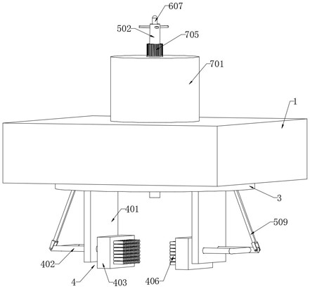
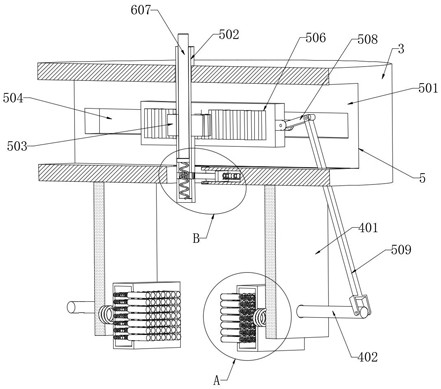
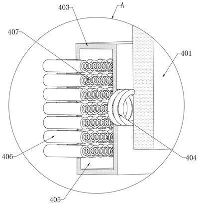
[0027] refer to Figure 1-7 , a clamping manipulator for capacitor production and processing, including a fixed plate 1, a circular groove 2 is opened at the lower end of the fixed plate 1, and a disc 3 is slidably connected to the inner wall of the circular groove 2, and a disc 3 is provided on the disc 3 to clamp the capacitor. The clamping mechanism 4, the clamping mechanism 4 includes two vertical plates 401 fixedly connected to the lower end of the disc 3, the side walls of the vertical plates 401 are slidably connected to the driving rod 402, and one end of the driving rod 402 is fixedly connected to the splint 403, and the side of the splint 403 The wall is elastically connected to the side wall of the vertical plate 401 through the first spring 404. A cavity 405 is opened in the splint 403. The inner wall of the cavity 405 is evenly distributed and slidably connected with a plurality of clamping rods 406. One end of the clamping rod 406 located in the cavity 405 passes ...


PUM


Abstract

The invention discloses a clamping manipulator used for producing and processing capacitors, which comprises a fixing plate, a circular groove is opened at the lower end of the fixing plate, a disk is slidably connected to the inner wall of the circular groove, and a pair of capacitors is arranged on the disk. A clamping mechanism for clamping, the clamping mechanism includes two vertical plates fixedly connected to the lower end of the disc, the side walls of the vertical plates are slidably connected to a driving rod, and one end of the driving rod is fixedly connected to a splint, the The side wall of the splint is elastically connected with the side wall of the riser through the first spring. The multiple clamping rods of the present invention can be extruded to form a shape that fits with the capacitor, and then can clamp capacitors of different shapes, and the unextruded clamping rods can also protect the capacitor from colliding during transportation Compared with the prior art, it can hold capacitors of different shapes, and no matter what position the capacitor is in, it can hold it stably by itself, without excessive operation, and has strong practicability.

Description

technical field [0001] The invention relates to the technical field of clamping manipulators, in particular to a clamping manipulator used for capacitor production and processing. Background technique [0002] Clamping manipulators are used in industry to clamp and transport objects to be processed. [0003] In the invention patent "a capacitor clamping mechanism" with the application number "201710899068.1", the solution is equipped with horizontal and vertical clamping claws, which can be driven by gears, rotating discs, cross-rotating frames, etc. according to the placement state of the capacitors. connection, freely control the clamping claws to be vertical or horizontal, to achieve a firm clamping of the capacitor, but there are still the following problems in this solution: [0004] 1. The horizontal and vertical clamping claws are set in an arc structure, so the clamping effect is better for cylindrical capacitors, but the appearance and shape of capacitors are diffe...

Claims


Application Information

Patent Timeline
Patent Type & Authority Patents(China)
IPC IPC(8): B65G47/90B65G47/244H01G13/00
CPCB65G47/90B65G47/244H01G13/00
Inventor 邵淋锋
Owner 南通海美电子有限公司
Why Eureka
Try Eureka