
Smart city security intelligent lamp pole control method

A control method and technology for light poles, applied in the field of Internet of Things, can solve the problems of navigation errors, time-consuming and laborious, affecting user travel experience, etc., to achieve the effect of improving accuracy and safety, and saving workload

Pending Publication Date: 2021-11-19
福建睿思特科技股份有限公司
View PDF0 Cites 0 Cited by
  • Summary
  • Abstract
  • Description
  • Claims
  • Application Information

AI Technical Summary

Problems solved by technology

On some overpass roads, because some roads overlap with each other, GPS navigation can obtain its positioning information, but it cannot accurately know which road the navigation terminal is driving on, resulting in navigation errors, which often require a long long road , affecting the travel experience of users
In addition, in the prior art, terrain measurement is generally performed manually by engineers and technicians, which is time-consuming and laborious

Method used


Image

  • Smart city security intelligent lamp pole control method
  • Smart city security intelligent lamp pole control method
  • Smart city security intelligent lamp pole control method

Examples


Embodiment Construction

[0026] Below in conjunction with accompanying drawing and embodiment the present invention will be further described:

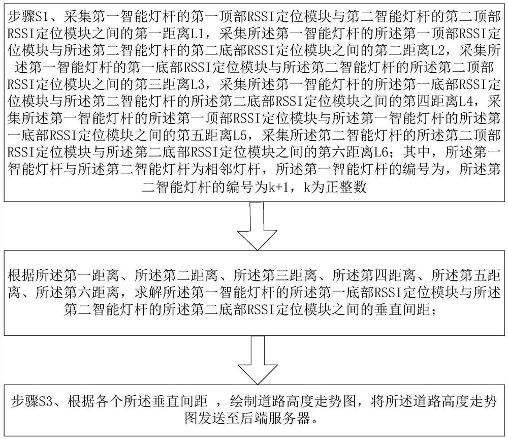
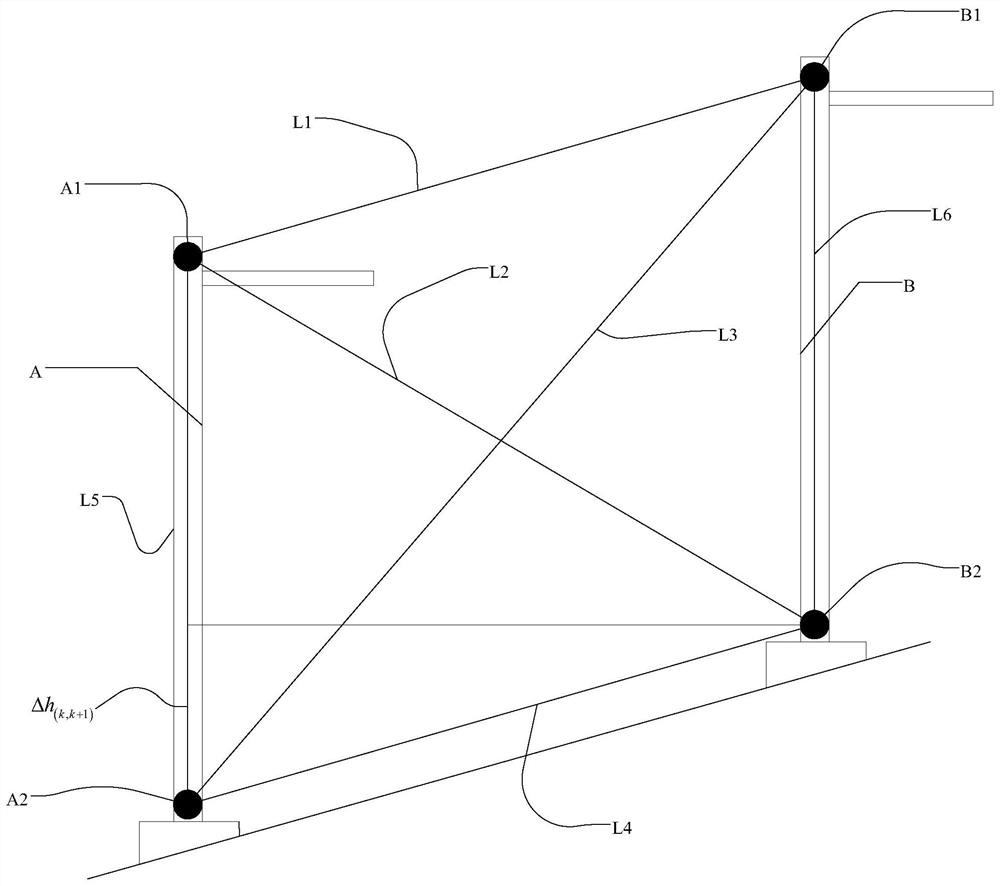
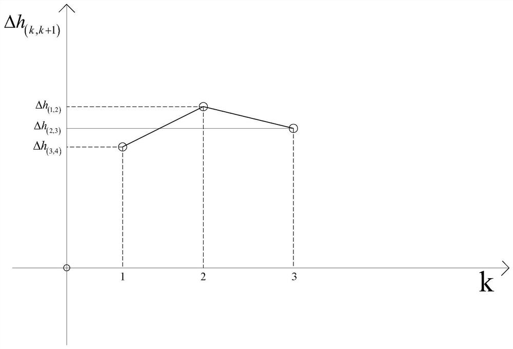
[0027] like Figure 1-3 , in the first embodiment of the present invention, a smart city security smart light pole control method includes: a light pole body, a top RSSI positioning module set on the top of the light pole body, a top RSSI positioning module set on the bottom of the light pole body Bottom RSSI positioning module; the smart light pole is used along the smart city road, and at least three smart light poles are arranged at continuous intervals along the smart city road, and the smart light pole is installed vertically; the method includes :

[0028] Step S1, collect the first distance L between the first top RSSI positioning module A1 of the first smart light pole A and the second top RSSI positioning module B2 of the second smart light pole B 1 Collecting a second distance L between the first top RSSI positioning module A1 of the first smart l...


PUM


Abstract

The invention discloses a smart city security intelligent lamp pole control method and relates to the field of Internet of Things. The smart city security intelligent lamp pole control method comprises a lamp pole body, a top RSSI positioning module arranged at the top of the lamp pole body, and a bottom RSSI positioning module arranged at the bottom of the lamp pole body, intelligent lamp poles are used along a smart city road, and at least three intelligent lamp poles are continuously arranged along the smart city road at intervals. The control method comprises the following steps that firstly, concrete between the RSSI positioning modules is collected; then, the vertical distance of each RSSI positioning module is calculated; and finally, a road trend chart is drawn according to the vertical distance, the RSSI positioning modules are arranged at the tops and the bottoms of the intelligent lamp poles, the height difference between every two adjacent intelligent lamp poles can be calculated, and the road trend chart is drawn on the basis of the height difference. and meanwhile, the workload of manually measuring the road physical gradient is omitted, and precision and safety of navigation service are improved.

Description

technical field [0001] The invention relates to the field of the Internet of Things, in particular to a control method for a smart city security smart light pole. Background technique [0002] With the development of society, urban infrastructure has begun to develop in the direction of automation and intelligence. As the most common infrastructure, street lamps not only have the functions of lighting, beauty and road signs, but also can be used as a medium for publicity and guidance. [0003] In urban construction, smart light poles have also been more and more widely used. In addition to lighting the road, the smart light pole integrates multiple functions such as voice broadcasting, display modules, and signage. It has been welcomed and recognized by the market. With the rapid development of my country's tourism industry, in some tourist cities such as: Shanghai, Beijing, Chongqing, Xi'an and so on. Cities in central my country, such as Chongqing, are built on uneven ...

Claims


Application Information

Patent Timeline
IPC IPC(8): G01C21/28G01C5/00G01C9/00H04B17/318
CPCG01C21/28G01C5/00G01C9/00H04B17/318
Inventor 廖兴旺
Owner 福建睿思特科技股份有限公司
Learn More