Force-displacement measuring device and measuring method

A technology of displacement measurement and integration, which is applied in the direction of measuring devices, mechanical measuring devices, force/torque/power measuring instruments, etc., can solve the problems of damage to parts and measuring tools, long measurement cycle, and difficult measurement, so as to improve measurement accuracy , shorten the measurement cycle, optimize the effect of arm length

Pending Publication Date: 2021-11-19
SHAANXI AIRCRAFT CORPORATION
View PDF12 Cites 0 Cited by
  • Summary
  • Abstract
  • Description
  • Claims
  • Application Information

AI Technical Summary

Problems solved by technology

This measurement method requires the close cooperation of 3 people, poor force stability, long measurement cycle, poor measurement accuracy, etc. It is difficult to measure, and it is easy to cause damage to parts and measurement tools and personal injury.

Method used


Image

  • Force-displacement measuring device and measuring method
  • Force-displacement measuring device and measuring method
  • Force-displacement measuring device and measuring method

Examples


Embodiment 1

[0047] A kind of force-displacement measuring device and measuring method of the present invention are described in detail in conjunction with accompanying drawing:

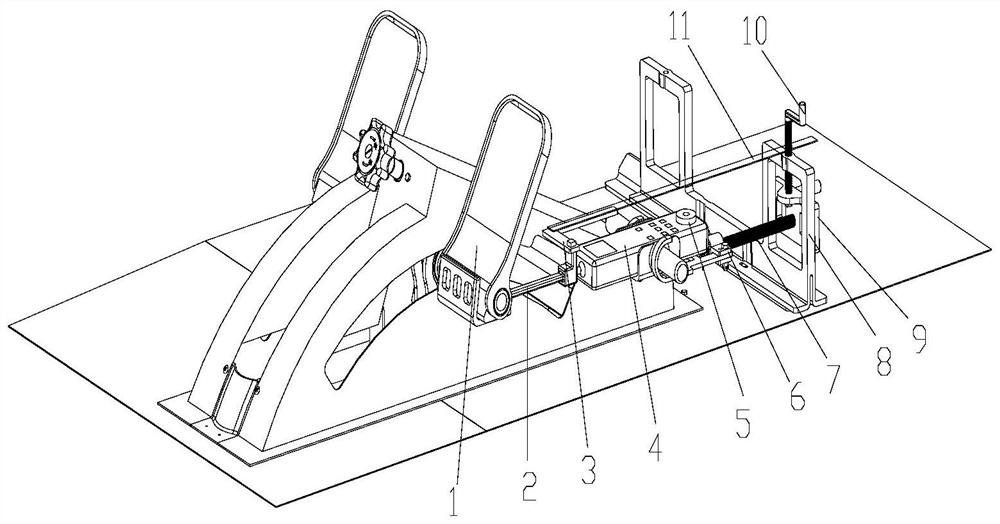
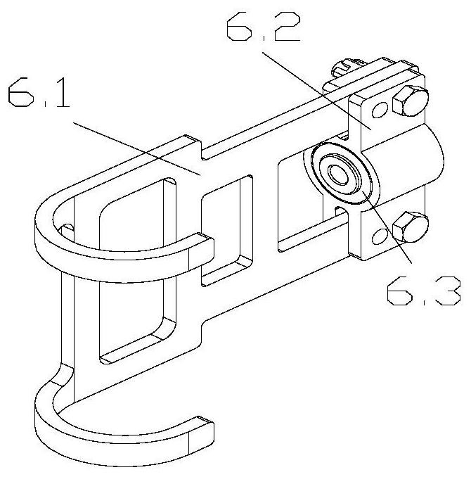
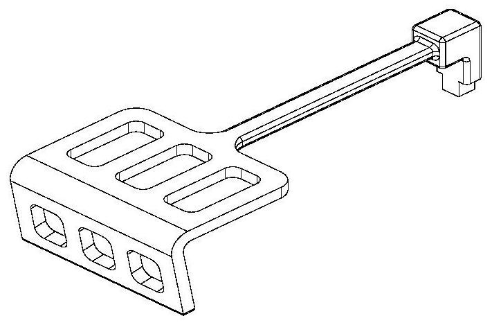
[0048] Such as figure 1 As shown, an assembly diagram of a force-displacement measuring device is provided, and the force-displacement measuring device includes a foot manipulation mechanism 1, a pull block 2, a crooked arm 3, a push-pull force gauge 4, a universal horizontal bubble 5, and a hook 6 , long leading screw 7, support 8, small slide block 9, short leading screw 10 and ruler 11. Such as figure 2 As shown, the structure of the hook 6 includes a hook 6-1, a connecting piece 6-2, and a bearing 6-3.

[0049] see figure 1 , figure 2 , image 3 , Figure 4 , one end of the pull block 2 is in contact with the foot control mechanism 1, the other end of the pull block 2 is screwed to the push-pull force gauge 4, the middle part of the pull block 2 is connected to the crooked arm 3 through a card slot; o...

Embodiment 2

[0051] Described a kind of force-displacement measuring device measurement process method is as follows:

[0052] first step, see figure 2 Compress the bearing 6-3 on the connector 6-2, and then screw it together with the hook 6-1

[0053] The second step, seefigure 1 , Figure 4 The bracket 8 is installed on the aircraft structure, and the screw connection is firm or directly placed on the structural inverted "T" profile.

[0054] The third step, see figure 1 The bracket 8 and the small slider 9 are connected together through a short lead screw 10 .

[0055] The fourth step, see figure 1 The small slide block 9 is connected with the hook 6 through the long lead screw 7.

[0056] Step five, see figure 1 One end of the pull block 2 is contacted with the foot control mechanism 1, and the other end is screwed together with the push-pull force gauge 4 through threads, and the crooked arm 3 is placed on the pull block 2 at a position close to it.

[0057] The sixth step, se...


PUM


Abstract

The invention provides a force-displacement measuring device which comprises a foot control mechanism 1, a pull block 2, an inclined arm 3, a pull and push dynamometer 4, a universal horizontal bubble 5, a hook 6, a long lead screw 7, a support 8, a small sliding block 9, a short lead screw 10 and a ruler 11, the hook 6 comprises a hook body 6-1, a connecting piece 6-2 and a bearing 6-3, one end of the pull block 2 is in contact connection with the foot control mechanism 1, the other end of the pull block 2 is screwed with the pull-push dynamometer 4, and the middle part of the pull block 2 is connected with the inclined arm 3; one end of the pull-push dynamometer 4 is in threaded connection with the pull block 2, the middle of the pull-push dynamometer 4 is in contact connection with the hook 6, and the universal horizontal bubble 5 is placed on the upper surface of the pull-push dynamometer 4; one end of the hook 6 is in contact connection with the pull-push dynamometer 4, and the other end of the hook 6 is in contact connection with the long lead screw 7 through the bearing 6-3; one end of the long lead screw 7 is in contact connection with the bearing 6-3, and the other end of the long lead screw 7 is connected with the small sliding block 9; and the upper end of the small sliding block 9 is in contact connection with the short lead screw 10, and the middle of the small sliding block 9 is in contact connection with the long lead screw 7.

Description

technical field [0001] The invention belongs to the technical field of aviation assembly, and in particular relates to a force-displacement measuring device and a measuring method. Background technique [0002] The foot control mechanism used by our company's Yunjiu series aircraft is installed behind the frame 2 of the front cabin, where the construction space is narrow and there are many shelters. In the force-displacement measurement process of the foot control mechanism, three people are required to cooperate to complete the force-displacement measurement of the foot control mechanism. In the previous measurement process, one person was required to hold the force measurement tool of the foot control mechanism, one person stepped on the force measurement tool of the foot control mechanism, and one person measured the displacement of the foot control mechanism. When the displacement of the foot-operating mechanism reaches a given value, the person who measures the displac...

Claims


Application Information

Patent Timeline
Patent Type & Authority Applications(China)
IPC IPC(8): G01L5/00G01B5/02G01M13/00
CPCG01L5/00G01B5/02G01M13/00
Inventor 唐永红李颢王春艳王舟李丹韩敏
Owner SHAANXI AIRCRAFT CORPORATION
Why Eureka
Try Eureka