Vehicle trajectory prediction method and device, equipment and storage medium
A technology of vehicle trajectory and prediction method, which is applied to control devices, vehicle components, road vehicle drive control systems, etc., can solve the problems of low accuracy of prediction results, large vehicle signal dependence, and low prediction efficiency, and achieves improved calculation accuracy. and efficiency, improve expression ability and calculation accuracy, and improve the effect of accuracy
- Summary
- Abstract
- Description
- Claims
- Application Information
AI Technical Summary
Problems solved by technology
Method used
Image
Examples
no. 1 example
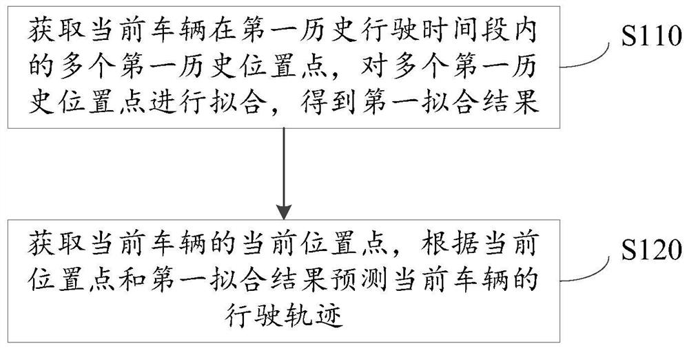
[0071] figure 1 It is a schematic flowchart of a vehicle trajectory prediction method provided according to the first embodiment of the present application. This embodiment is used to predict the trajectory of a driving vehicle. The method can be executed by a vehicle trajectory prediction device. The device It can be realized by means of software and / or hardware, and can be integrated into an electronic device, and the electronic device can be a device such as a vehicle-mounted terminal. like figure 1 As shown, a vehicle trajectory prediction method provided in this embodiment may include:
[0072] S110. Obtain multiple first historical location points of the current vehicle within the first historical driving time period, and perform fitting on the multiple first historical location points to obtain a first fitting result.
[0073] Wherein, the output results of GPS (Global Positioning System, Global Positioning System) and IMU (Inertial Measurement Unit, Inertial Measurem...
no. 2 example
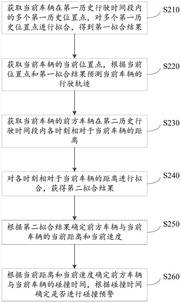
[0087] figure 2 It is a schematic flowchart of a vehicle trajectory prediction method provided according to the second embodiment of the present application. This embodiment is optimized on the basis of the above-mentioned embodiments, and is used for collision warning of driving vehicles. The method can be implemented by a vehicle The trajectory prediction device can be used to implement the device, which can be implemented in the form of software and / or hardware, and can be integrated into electronic equipment such as vehicle terminals. like figure 2 As shown, a vehicle trajectory prediction method provided in this embodiment may include:
[0088] S210. Obtain multiple first historical location points of the current vehicle within the first historical driving time period, and perform fitting on the multiple first historical location points to obtain a first fitting result.
[0089] S220. Obtain the current location point of the current vehicle, and predict the driving tr...
no. 3 example
[0110] Figure 5 It is a schematic structural diagram of a vehicle trajectory prediction device according to the third embodiment of the application, which can execute the vehicle trajectory prediction method provided in the embodiment of the application, and has corresponding functional modules and beneficial effects for executing the method. like Figure 5 As shown, the device 500 may include:
[0111] The first fitting result obtaining module 501 is used to obtain a plurality of first historical position points of the current vehicle within the first historical driving time period, and perform fitting on the plurality of first historical position points to obtain a first fitting result;
[0112] The driving trajectory prediction module 502 is configured to obtain the current location point of the current vehicle, and predict the driving trajectory of the current vehicle according to the current location point and the first fitting result.
[0113] Optionally, the first hi...
PUM
 Abstract
Description
Claims
Application Information
 - R&D
- Intellectual Property
- Life Sciences
- Materials
- Tech Scout
- Unparalleled Data Quality
- Higher Quality Content
- 60% Fewer Hallucinations
Browse by: Latest US Patents, China's latest patents, Technical Efficacy Thesaurus, Application Domain, Technology Topic, Popular Technical Reports.
© 2025 PatSnap. All rights reserved.Legal|Privacy policy|Modern Slavery Act Transparency Statement|Sitemap|About US| Contact US: help@patsnap.com


