Cable stripping device for power supply system
A power supply system and cable technology, which is applied in the field of cable stripping devices for power supply systems, can solve the problems of easily scratching the palms of personnel, affecting the health of workers, cable damage or breakage, etc., so as to reduce contact with cables and reduce scratches on palms , the effect of easy operation
- Summary
- Abstract
- Description
- Claims
- Application Information
AI Technical Summary
Problems solved by technology
Method used
Image

Examples
Embodiment 1
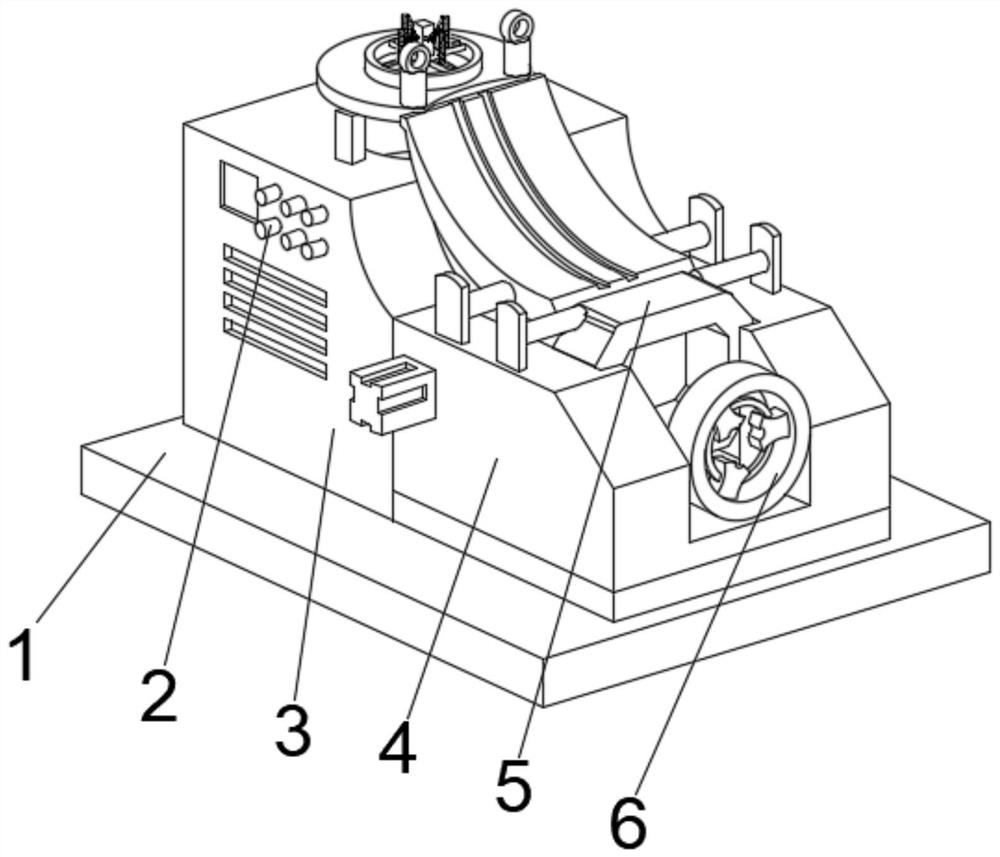
[0035] See Figure 1-2The present invention provides a technical solution: a cable peeled device for a power supply system, including a bottom plate 1, and a power-on-side position of the top left side of the bottom plate 1, and the power box 3 is fixed. The control panel 2, the right side of the power box 3 is fixed to the position of the protective frame 4, and the protective frame 4 is adjacent to the power box 3 is provided with a peeled device 5, and the protective frame 4 is fixed from the middle of one side of the power cartridge 3 fixedly connected to the cable tight. Firmware 6.
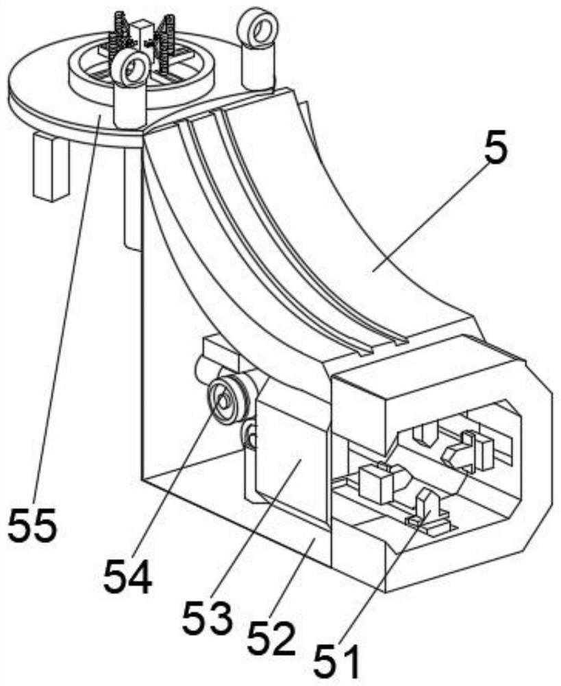
[0036] Wherein, the peeled device 5 includes a fixed connection frame 52, and the position of the positioning transmission frame 54 is fixedly connected to the left inner wall bottom of the fixed connection frame 52, and the top outer wall of the fixed connection frame 52 is fixedly connected to the collecting mechanism 55, and the fixed connection frame 52 The outer outer wall is provided with a...
Embodiment 2
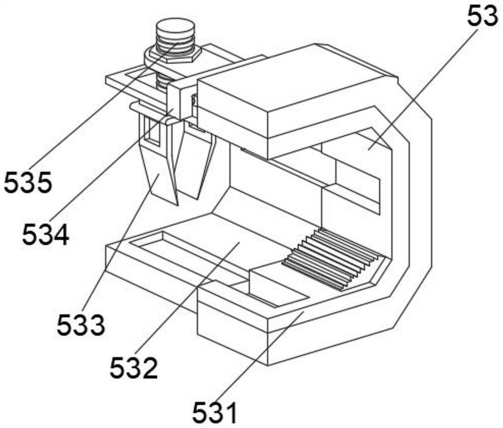
[0039] See Figure 1-4 Based on the first example, the present invention provides a technical solution: the member of the adjustment mechanism 53 includes a modulation body 532, and the right side wall of the adjustment body 532 is fixedly connected to the frame 531, and the top right side of the adjustment body 532 is fixed. There is a connection plate 534, and the connection plate 534 is adjusted to the position of the frame 531, and the bottom portion of the adjustment conductor 535 is adjusted to the inside of the adjustment body 532, and the bottom fixing of the adjustment conductor 535 is fixedly connected to the auxiliary contact frame. 533.
[0040] Wherein, the component of the collecting mechanism 55 includes a collecting disk 553, and the bottom intermediate position of the collecting disk 553 is fixedly connected to the link shaft 551, and the top intermediate position of the collecting disk 553 is fixedly connected to the collecting control frame 555, and the top of th...
Embodiment 3
[0043] See Figure 1-6 In the basis of the first embodiment, the present invention provides a technical solution: the member two of the adjustment mechanism 53 includes a guide block D1, and the outer wall fixing of the guide block D1 is fixedly connected to the inner solid D3, and the solid D3 is close to The outer walls of the guide block D1 are connected to the wind turbine D2, and the inner wall of the inner wall of the solid D3 is provided with a rotating fixed ring D5, and the solid D3 is fixed to the position of the wind turbine D2, and the increased contact plate D4 is fixed.
[0044] Wherein, the member two of the collecting mechanism 55 includes the upper rotation module T1, and the intermediate position of the upper rotation module T1 is provided with the collector T2, and the middle portion of the collecting fastener T2 is set to have a collecting guide block T4, collecting the fastener. The outer surface of the T2 is provided with the positioning limiter T3, and the bo...
PUM
 Abstract
Description
Claims
Application Information
 - R&D
- Intellectual Property
- Life Sciences
- Materials
- Tech Scout
- Unparalleled Data Quality
- Higher Quality Content
- 60% Fewer Hallucinations
Browse by: Latest US Patents, China's latest patents, Technical Efficacy Thesaurus, Application Domain, Technology Topic, Popular Technical Reports.
© 2025 PatSnap. All rights reserved.Legal|Privacy policy|Modern Slavery Act Transparency Statement|Sitemap|About US| Contact US: help@patsnap.com