Check patentability & draft patents in minutes with Patsnap Eureka AI!

Method for determining PUSCH transmission parameters and communication device

A technology for transmission parameters and determination methods, applied in wireless communication, electrical components, etc., can solve the problems of high equivalent transmission code rate systems, few Actualrepetition resources, and inability to transmit bits, so as to improve system performance and improve decoding accuracy. effect of probability

Pending Publication Date: 2021-11-19
VIVO MOBILE COMM CO LTD
View PDF0 Cites 0 Cited by
  • Summary
  • Abstract
  • Description
  • Claims
  • Application Information

AI Technical Summary

Problems solved by technology

[0005] Embodiments of the present invention provide a method for determining PUSCH transmission parameters and a communication device, which are used to solve the problem that due to Nominal repetitions being segmented, actual resources available for Actual repetition are less, so that the actual equivalent transmission code rate is relatively high or a certain The problem that some system bits cannot be transmitted

Method used


Image

  • Method for determining PUSCH transmission parameters and communication device
  • Method for determining PUSCH transmission parameters and communication device
  • Method for determining PUSCH transmission parameters and communication device

Examples


Embodiment 1

[0175] Such as Figures 6a-6g , gives the available time-domain resource distribution of 8 actual repetition transmissions for repetition transmission, using LDPC base graph 2, the RV sequence configured on the network side is {0,2,3,1}, and the RV start position configured on the network side The table is shown in Table 1, that is, the starting position corresponding to RV0 is 0, and the starting position corresponding to RV1 is The starting position corresponding to RV2 is The starting position corresponding to RV3 is

[0176] For example, the first condition at this time is that the actually available time-domain symbols (available transmission resources) are smaller than the configured number of nominal repetition time-domain symbols (target resources).

[0177] Such as Figure 6a , the current PUSCH repeated transmission uses RV0, and the RV start position is 0.

[0178] Such as Figure 6b , the current PUSCH repeated transmission uses RV2, and the starting posit...

Embodiment approach 2

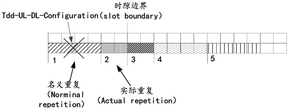
[0185] Figure 7 is the resource distribution in the time domain of the actual repeated transmission (actual repetition) in the embodiment of the present invention:

[0186] For the first actual repetition, determine the corresponding mapping method according to the RRC configuration or protocol;

[0187] Please refer to Figure 8 , since the available time domain resources (available transmission resources) of the first actual repetition are less than 1 / 2 (target resources) of the time domain resources required for nominal repetition transmission, the second actual repetition transmission continues to transmit the remaining symbols (symbols ) (modulation symbol); and the third actual repetition transmission does not satisfy the first condition, and will continue to map all transport blocks (TB).

[0188] In fact, for the second actual repetition transmission, in some cases, the demodulation reference signal (Demodulation Reference Signal, DMRS) symbols may not be mapped, so...


PUM


Abstract

Provided in an embodiment of the present invention are a method for determining PUSCH transmission parameters and a communication device. The method for determining PUSCH transmission parameters comprises the steps of: for a current PUSCH repeated transmission in a plurality of PUSCH repeated transmissions, determining a transmission parameter of the current PUSCH repeated transmission according to a transmission resource of the PUSCH repeated transmission, the transmission parameter comprising at least one of the following items: RV; an RV initial position; a PUSCH mapping mode. In the embodiment of the invention, a method for determining the RV, the RV initial position and / or the PUSCH mapping mode is provided for Actual reppetition transmission in multiple PUSCH repeated transmission, so that the problem that the actual effective code rate is relatively high or a part of system bits cannot be transmitted in Actual repetition transmission can be solved, the decoding correctness probability of a receiving end is improved, and the system performance is improved.

Description

technical field [0001] The embodiments of the present invention relate to the technical field of wireless communication, and in particular to a method for determining a PUSCH transmission parameter and a communication device. Background technique [0002] A physical uplink shared channel (Physical Uplink Shared Channel, PUSCH) repetition (repetition) type B (type B) uses multiple nominal repetitions (Nominal repetitions) to transmit the PUSCH. [0003] Nominal repetitions may be further segmented to form a series of actual repetitions (Actual repetitions), these Actual repetitions are for a single transport block (Transport Block, TB) or hybrid automatic repeat request scheduled for downlink control information (Downlink Control Information, DCI) Repeated transmission of (Hybrid Automatic Repeat reQuest, HARQ) process. [0004] However, if Actual repetition actually has fewer resources available, the actual equivalent transmission code rate is higher, or some systematic bit...

Claims


Application Information

Patent Timeline
Patent Type & Authority Applications(China)
IPC IPC(8): H04W24/02
CPCH04W24/02
Inventor 王勇顾一
Owner VIVO MOBILE COMM CO LTD
Features
  • R&D
  • Intellectual Property
  • Life Sciences
  • Materials
  • Tech Scout
  • Unparalleled Data Quality
  • Higher Quality Content
  • 60% Fewer Hallucinations
Learn More