Location system

a technology of location system and location location, which is applied in the field of location system, can solve the problems of affecting the identity and position affecting the transmission, and affecting the accuracy of the deter mining tag, so as to reduce the processing power, reduce the cost, and reduce the power consumption

Active Publication Date: 2014-06-19
SONITOR TECH
View PDF5 Cites 8 Cited by
  • Summary
  • Abstract
  • Description
  • Claims
  • Application Information

AI Technical Summary

Benefits of technology

[0027]In some embodiments one or more of the static stations may comprise some or all of the processing means, or the processing means may be external to the mobile units and the static stations, e.g. on one or more external servers. This may be advantageous since minimizing the processing power required on the mobile units can reduce their cost and can reduce power consumption, even after accounting for the need to transmit data from the mobile unit, which is especially useful when they are battery powered. The processing means may be split across multiple processors or multiple locations, or both. The r

Problems solved by technology

Such an approach has limitations.
In particular, its accuracy in deter mining the identity and position of the tag can be adversely affected by multi-path interference, which is commonly present due to reflections of the transmitted signal from walls, ceilings and other surfaces.
It can also fail to recognize a tag which is moving and thereby creating a Doppler shift in the received signals.
It is als

Method used


Image

  • Location system
  • Location system
  • Location system

Examples


Embodiment Construction

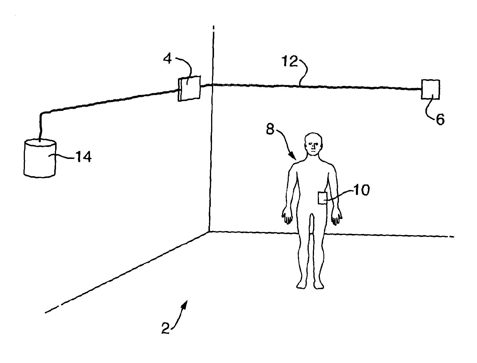
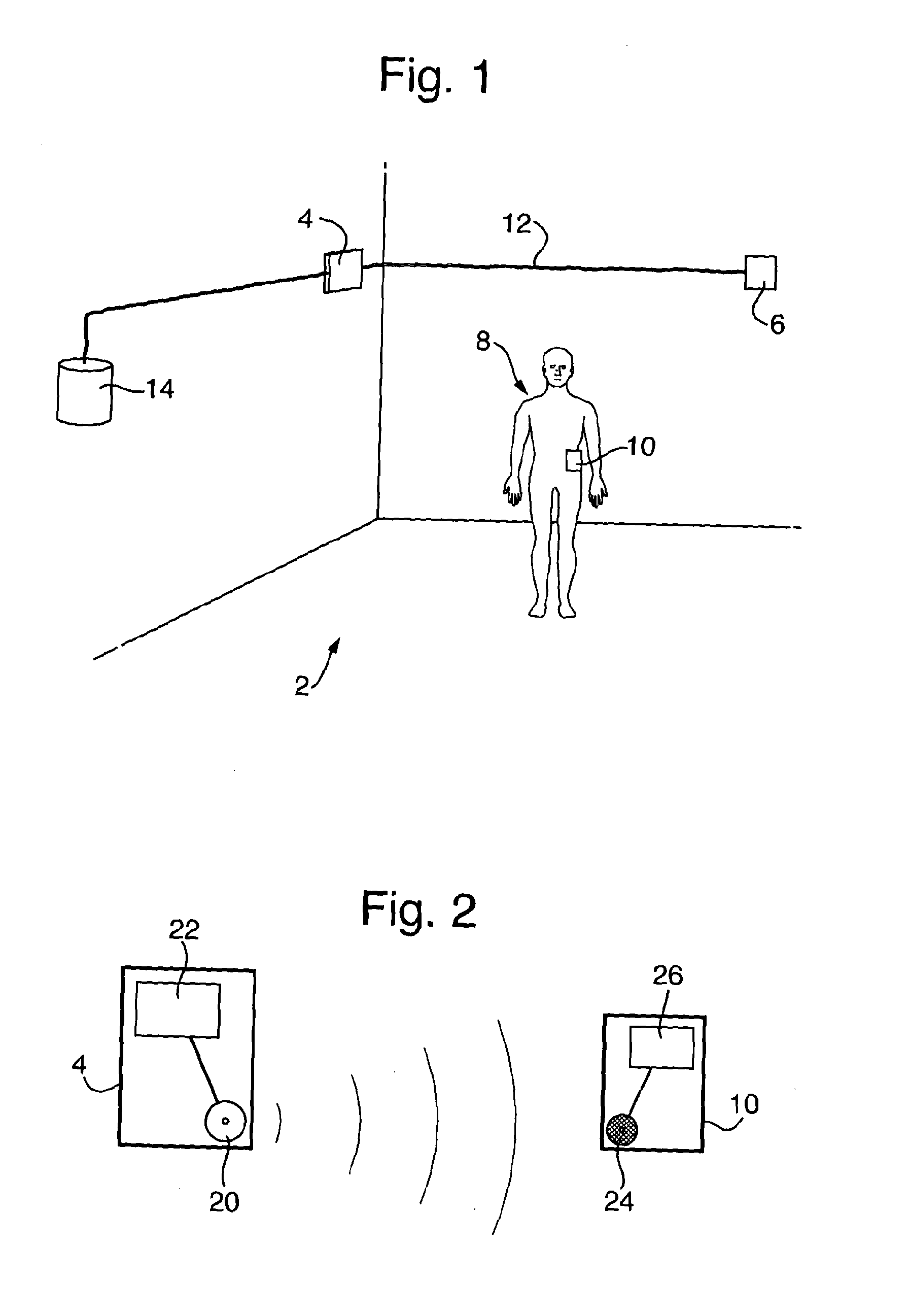
[0088]FIG. 1 shows a room 2, to the walls of which are affixed a first static transmitter station 4 and a second static transmitter station 6. A person 8 in the room is carrying a mobile receiver unit 10. A network cable 12 connects the two transmitter stations 4, 6 to a server 14.

[0089]FIG. 2 shows the first transmitter station 4, which has an ultrasonic sounder 20 and processing logic 22 for causing the ultrasound sounder 20 to transmit ultrasonic signals. The second transmitter station 6 has the same configuration. FIG. 2 also shows the mobile receiver unit 10, which has a microphone 24 capable of receiving ultrasonic signals from the transmitter station 4, and processing logic 26 for sampling and processing received signals.

[0090]In use, the server 14 causes each transmitter station 4, 6 to transmit, at intervals, a signature unique to that transmitter station. The server 14 may also instruct one or both transmitter stations 4, 6 to transmit information to the mobile receiver un...


PUM


Abstract

Static transmitter stations are used to determine the position of a mobile receiver unit. Each transmitter station transmits an ultrasonic signal including a transmitter-specific phase-shifting signature. The receiver unit receives a signal and identifies a transmitter station by its signature. It uses the received signal and the identity of the source transmitter station to determine the position of the mobile receiver unit. The signature may include two patterns phase-shift-key (PSK)-encoded on respective carrier signals of the same frequency but different phase, with the patterns being offset from each other by a transmitter-specific offset. The signal from the transmitter station may also include a PSK-encoded message.

Description

[0001]This application is entitled to the benefit of, and incorporates by reference essential subject matter disclosed in PCT Application No. PCT / GB2012 / 050781 filed on Apr. 5, 2012, which claims priority to GB1105902.9 filed Apr. 7, 2011.BACKGROUND OF THE INVENTION[0002]1. Technical Field[0003]This invention relates to systems and methods for determining the position of a mobile unit using ultrasound.[0004]2. Background Information[0005]There are many situations in which it is desirable to be able to determine the location of a moveable object, such as a person or an item of equipment, within an area such as a hospital ward.[0006]It is known to provide a network of static base stations, e.g. attached to ceilings or walls, and to attach ultrasonic tags to moveable objects which communicate with one or more of the base stations so as to allow the location of the tagged object to be determined. Ultrasound is well suited to this purpose as it is undetectable to humans It also travels m...

Claims


Application Information

Patent Timeline
IPC IPC(8): G01S5/18H04L27/18
CPCH04L27/18G01S5/18G01S1/725G01S1/805G01S5/26G01S5/30G01S1/75H04B11/00G01S1/807
Inventor BOOIJ, WILFRED EDWINOLSEN, OYSTEIN HAUG
Owner SONITOR TECH
Why Eureka
Try Eureka