Supercharge Your Innovation With Domain-Expert AI Agents!

Simple shaft platform

A shaft and platform technology, applied in the field of simple shaft platforms, can solve the problems of high purchase and transportation costs, consuming installation man-hours, and large overall weight, and achieve the effects of convenient installation and transportation, efficient use process, and simple use process.

Pending Publication Date: 2021-11-23
崔晓江
View PDF6 Cites 0 Cited by
  • Summary
  • Abstract
  • Description
  • Claims
  • Application Information

AI Technical Summary

Problems solved by technology

[0002] At present, various elevator manufacturers commonly use elevator shaft installation platforms, which are generally iron single-layer or double-layer platforms. , often use scaffolding pipes to build uncertified construction platforms privately, frequent safety accidents, and complex and cumbersome installation and construction operations

Method used


Image

  • Simple shaft platform
  • Simple shaft platform
  • Simple shaft platform

Examples


Embodiment 1

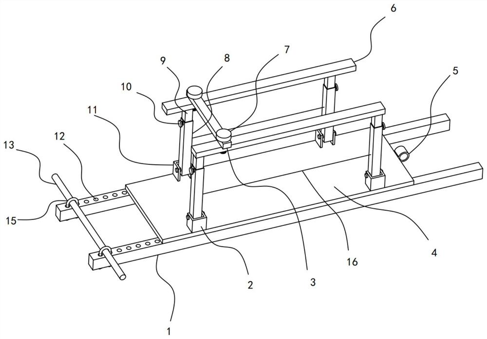
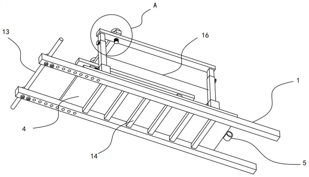
[0024] see Figure 1-3 , a simple hoistway platform, including a bearing plate 4, two parallel supporting strips 1 are installed on the bottom of the supporting plate 4, a pair of rotating seats I2 and a pair of rotating seats II11 are fixedly installed on the supporting plate 4, The distance between the two rotating seats I2 is less than the distance between the two rotating seats II11, each of the rotating seats I2 and each of the rotating seats II11 is hinged with a sleeve 8, and each of the sleeves 8 Lifting columns 9 are slidably installed on the top, and gear rods 6 are fixed on the lifting columns 9, and connecting strips 3 are fixed on the gear rods 6 .

[0025] When the platform is in use, one end of the support slat 1 is clamped on the side wall of the hoistway, the other end of the support slat 1 is set on the floor to which the hoistway belongs, and the set bearing plate 4 is used as a working platform for the staff to stand on. The provided sleeve pipe 8, lifting...

Embodiment 2

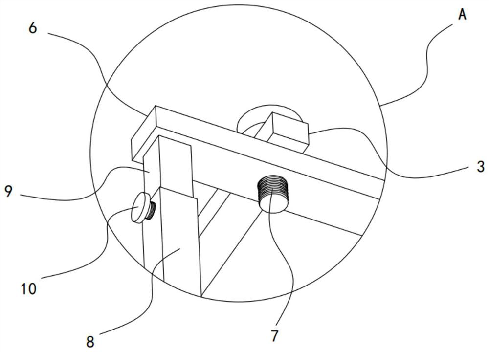
[0028] On the basis of Embodiment 1, in addition, the side wall of the casing 8 is threadedly connected with a locking stud II10, and the locking stud II10 abuts against the side wall of the lifting column 9, and slides relative to the casing 8 through the lifting column 9. The tightening stud II10 realizes the locking effect after the lifting height of the lifting column 9 is adjusted, realizes the flexible adjustment of the protection height range on both sides of the carrying plate 4, and is safer to use.

[0029] In addition, a locking stud I7 is pierced on the connecting strip 3, and the locking stud I7 extends into the gear rod 6 through a threaded connection. The stud I7 is locked to ensure the stability of the connection between the sleeve pipe 8, the lifting column 9, the gear lever 6 and the connecting strip 3.

[0030] Further, several mounting holes 12 are opened at equal intervals on each of the support strips 1 , each of the support strips 1 is equipped with buck...


PUM


Abstract

The invention discloses a simple shaft platform, and relates to the technical field of shaft platforms. The simple shaft platform comprises a bearing plate, two parallel supporting battens are installed at the bottom of the bearing plate, a pair of rotating seats I and a pair of rotating seats II are fixedly installed on the bearing plate, the distance between the two rotating seats I is smaller than the distance between the two rotating seats II, casing pipes are hinged to the rotating seats I and the rotating seats II respectively, a lifting column is slidably mounted on each casing pipe, and a gear lever is fixed to each lifting column. According to the simple shaft platform, the two supporting battens abut against the side wall of a shaft, therefore, the supporting effect on the whole platform is achieved, and the stability and firmness in the mounting process are ensured through the limiting effect of a horizontal column on the positions of the supporting battens. The casing pipes can achieve the folding effect, rapid installation is greatly facilitated, meanwhile, the lifting columns can slide relative to the casing pipes, the effect of flexibly adjusting the protection range is achieved, and the platform is simple and efficient in the using process.

Description

technical field [0001] The invention relates to the technical field of hoistway platforms, in particular to a simple hoistway platform. Background technique [0002] At present, various elevator manufacturers commonly use elevator shaft installation platforms, which are generally iron single-layer or double-layer platforms. , Often use scaffolding pipes to build uncertified construction platforms privately, frequent safety accidents, and complex and cumbersome installation and construction operations. [0003] Based on the actual situation of the prior art, a simple hoistway platform is proposed, which has the technical advantages of simple installation and high efficiency, so as to solve the above technical problems. Contents of the invention [0004] The purpose of the present invention is to provide a simple hoistway platform to solve the problems raised in the above-mentioned background technology. [0005] To achieve the above object, the present invention provides ...

Claims


Application Information

Patent Timeline
IPC IPC(8): B66B7/00E04G3/28
CPCB66B7/00E04G3/28E04G2003/286
Inventor 崔晓江卢笑培
Owner 崔晓江
Features
  • R&D
  • Intellectual Property
  • Life Sciences
  • Materials
  • Tech Scout
  • Unparalleled Data Quality
  • Higher Quality Content
  • 60% Fewer Hallucinations
Learn More