Working device position parameter data acquisition method and loader
A working device and data acquisition technology, which can be applied in the fields of earth movers/shovels, mechanically driven excavators/dredgers, construction, etc. Effect
- Summary
- Abstract
- Description
- Claims
- Application Information
AI Technical Summary
Problems solved by technology
Method used
Image

Examples
Embodiment Construction
[0028] The specific implementation will be described below in conjunction with the accompanying drawings.
[0029] Such as figure 1 figure 2 As shown, this embodiment provides a method for acquiring position parameter data of a working device, and the method is used to acquire position parameter data of a working device of a loader. The position parameter data of the working device is used for the automatic control of the loader.
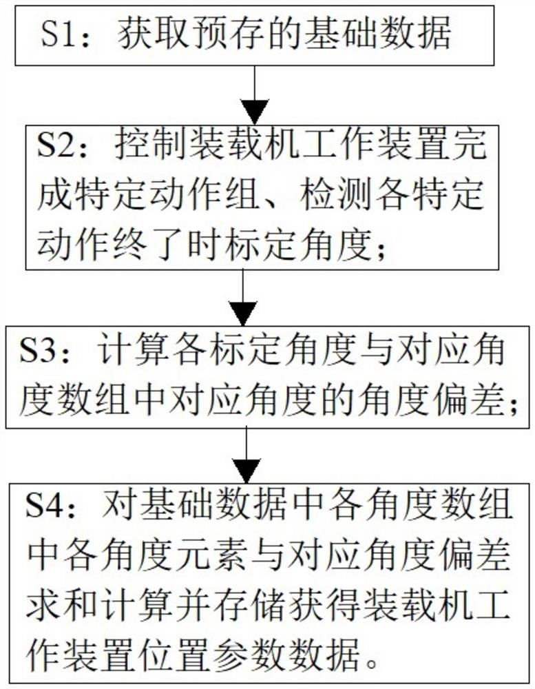
[0030] The steps of the location parameter data acquisition method are as follows:
[0031] S1: Obtain pre-stored basic data;
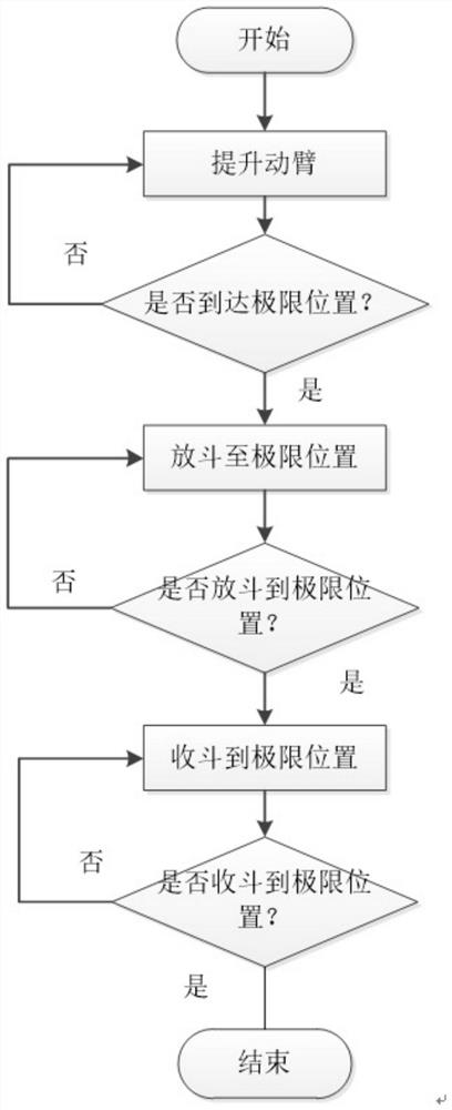
[0032] S2: Automatically control the working device of the loader through the control program to complete a specific action group and detect the calibration angle at the end of each specific action;
[0033] S3: Calculate the angle deviation between each calibration angle and the angle corresponding to the boom lifting limit position in the corresponding angle array;
[0034] S4: Calculate and store the sum of each an...
PUM
 Abstract
Description
Claims
Application Information