
Power generation mechanism filled with slurry

A technology for filling slurry and slurry, which is applied in the directions of filling materials, engine components, machines/engines, etc., can solve the problems of scrap drilling, waste of gravitational potential energy of slurry, large impact force, etc., and achieves good safety and energy utilization. High rate and the effect of reducing impact pressure

Pending Publication Date: 2021-11-23
本溪龙新矿业有限公司
View PDF0 Cites 0 Cited by
  • Summary
  • Abstract
  • Description
  • Claims
  • Application Information

AI Technical Summary

Problems solved by technology

When the filling slurry is transported in the special filling borehole for ultra-deep wells, an energy flow with high pressure head and high gravitational potential energy is formed, which forms a large pressure on the bottom of the filling borehole, and there is a hidden danger of pipe explosion and injury
And it will cause a large impact force on the contact point between the slurry and the vertical pipe. The long-term impact will damage the inner wall of the borehole. The hole is scrapped, and the gravitational potential energy of the slurry is wasted during the impact process, which is difficult to be effectively utilized

Method used


Image

  • Power generation mechanism filled with slurry
  • Power generation mechanism filled with slurry
  • Power generation mechanism filled with slurry

Examples


Embodiment Construction

[0032] Embodiments of the present invention are described in detail below, examples of which are shown in the drawings, wherein the same or similar reference numerals designate the same or similar elements or elements having the same or similar functions throughout. The embodiments described below by referring to the accompanying drawings are exemplary and are intended to explain the present invention, but cannot be construed as limitations to the present invention. Based on the embodiments in the present invention, those skilled in the art do not make creative work premise All other embodiments obtained below all belong to the protection scope of the present invention.

[0033] In describing the present invention, it should be understood that the terms "center", "longitudinal", "transverse", "length", "width", "thickness", "upper", "lower", "front", " Back", "Left", "Right", "Vertical", "Horizontal", "Top", "Bottom", "Inner", "Outer", "Clockwise", "Counterclockwise", "Axial",...


PUM


Abstract

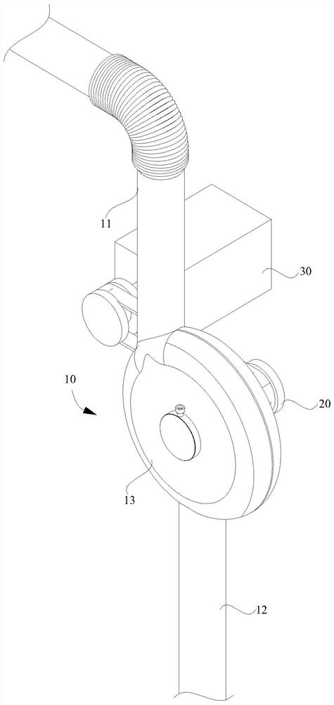
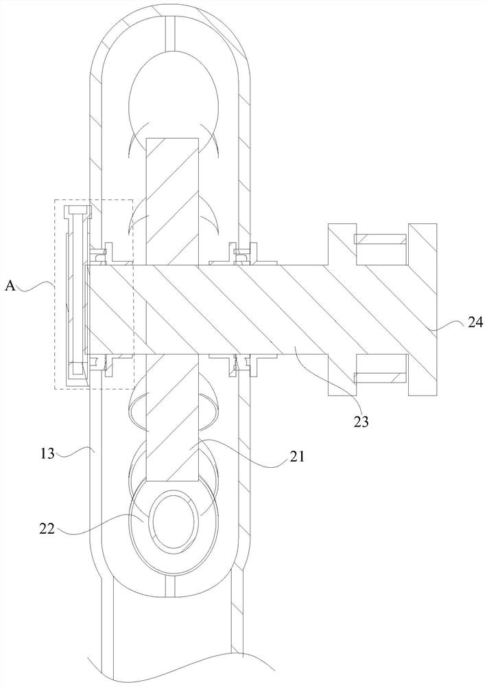
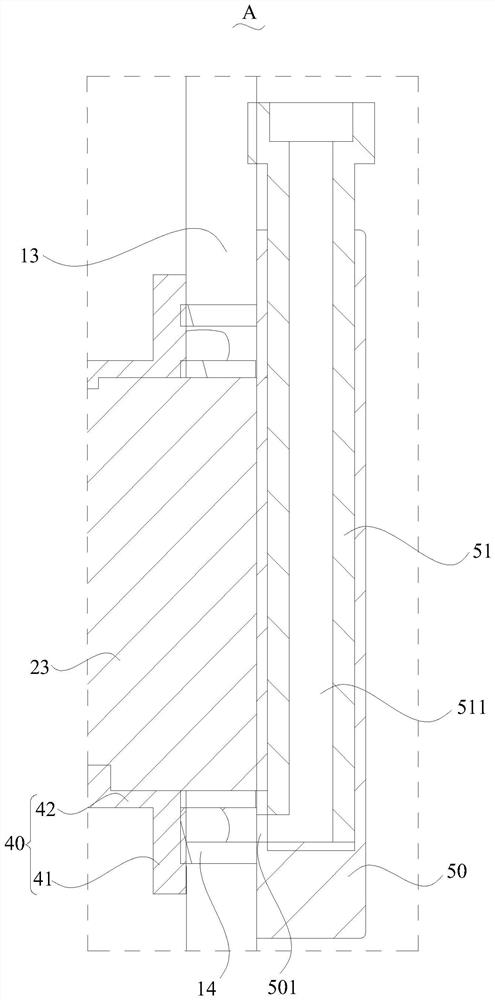
The invention discloses a power generation mechanism filled with slurry. The power generation mechanism comprises a pipe body, a buffer mechanism and a power generation device, wherein the pipe body is provided with a feeding channel and a discharging channel, buffer parts which are communicated with each other are arranged between the feeding channel and the discharging channel, and the buffer parts are used for allowing the slurry to enter through the feeding channel and to be discharged from the discharging channel; the buffer mechanism is rotatably arranged in the buffer parts, so that the slurry enters and impacts the buffer mechanism to rotate; and the power generation device is in transmission connection with the buffer mechanism, and when the slurry impacts the buffer mechanism to rotate, the power generation device rotates together with the buffer mechanism to convert the slurry into electric energy.

Description

technical field [0001] The invention relates to the technical field of power generation, in particular to a power generation mechanism for filling slurry. Background technique [0002] Metal and nonmetal underground mining mines generally have a well depth less than 500m, and when the well depth exceeds 700m, it is defined as an ultra-deep well. Underground mine filling refers to the use of tailings and cementitious materials according to a certain ratio to form a homogeneous two-phase flow filling slurry after being stirred evenly by a mixing tank, and then pumped to the underground goaf through a special filling hole for self-flow or pumping. After the slurry undergoes self-gelling reaction, it forms a filling body with certain compressive strength and self-supporting property, which is used to prevent surface subsidence and meet the follow-up mining work. [0003] Due to the deep depth of the existing ultra-deep mines, the vertical depth of the filling boreholes for subs...

Claims


Application Information

Patent Timeline
IPC IPC(8): F03B13/00F03B13/02E21F15/08
CPCF03B13/00F03B13/02E21F15/08
Inventor 杨宪礼李真李胜鹏海啸
Owner 本溪龙新矿业有限公司
Learn More