
Air extracting pump

A technology of air suction pump and pump casing, applied in the field of flow control, which can solve the problems of small exhaust volume and unable to meet the use requirements, and achieve the effects of increasing suction and displacement, increasing wind speed, and reducing volume

Active Publication Date: 2021-11-23
NINGBO JIAYIN ELECTRICAL & MECHANICAL TECH CO LTD
View PDF12 Cites 1 Cited by
  • Summary
  • Abstract
  • Description
  • Claims
  • Application Information

AI Technical Summary

Problems solved by technology

However, the air pump with the above-mentioned structure has a small exhaust volume during operation, which cannot meet the high requirements for the exhaust volume in steam ovens and other equipment.

Method used


Image

  • Air extracting pump
  • Air extracting pump
  • Air extracting pump

Examples


Embodiment Construction

[0029] The technical solutions in the embodiments of the present invention will be clearly and completely described below in conjunction with the accompanying drawings in the embodiments of the present invention. Obviously, the described embodiments are only part of the embodiments of the present invention, not all of them. Based on the implementation manners in the present invention, all other implementation manners obtained by persons of ordinary skill in the art without making creative efforts belong to the scope of protection of the present invention.

[0030] It should be noted that when an element is referred to as being “disposed on” another element, it may be directly disposed on the other element or there may be an intervening element. When an element is referred to as being "disposed on" another element, it can be directly on the other element or intervening elements may also be present. When an element is referred to as being "affixed to" another element, it can be ...


PUM


Abstract

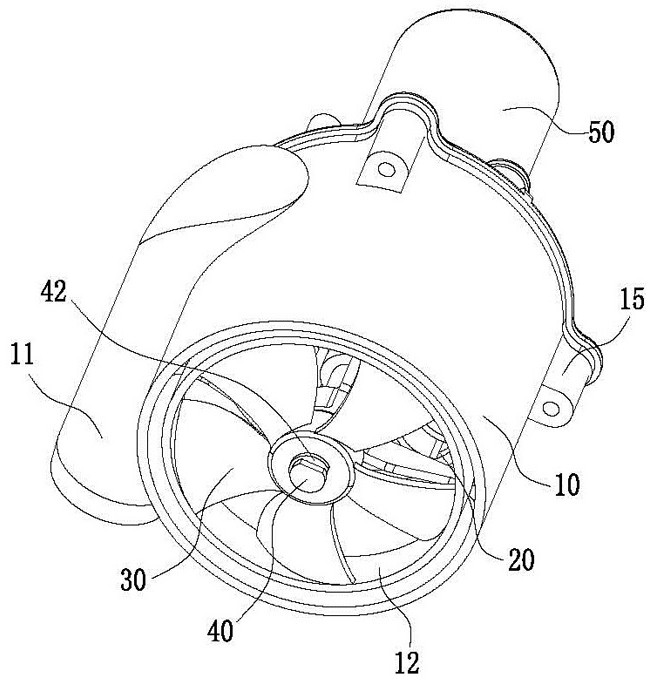
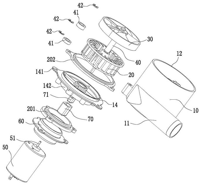
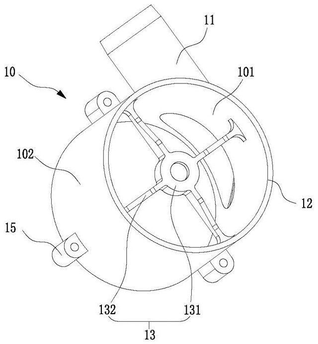
The invention relates to an air extracting pump which comprises a pump shell, centrifugal fan blades, axial flow fan blades and a rotating shaft. The centrifugal fan blades and the axial flow fan blades are arranged in the pump shell, the pump shell is connected and communicated with a ventilation pipe in the area where the centrifugal fan blades are located in the tangential direction of the pump shell, and the rotating shaft is limited to the centrifugal fan blades and the axial flow fan blades in the circumferential direction, so that the rotating shaft can drive the centrifugal fan blades and the axial flow fan blades to rotate relative to the pump shell at the same time, wherein the air displacement of the centrifugal fan blades during working is larger than that of the axial flow fan blades during working. According to the air extracting pump, the suction and discharge capacity of the air extracting pump in the whole working process can be improved, so that the large-discharge-capacity use requirement is met; and meanwhile, the axial flow fan blades and the centrifugal fan blades are arranged in the pump shell, so that the size can be reduced, miniaturization of the whole structure of the air extracting pump is achieved, and the using requirement for assembling of the air extracting pump in equipment is further met.

Description

technical field [0001] The invention relates to the technical field related to flow control, in particular to an air suction pump. Background technique [0002] At present, a centrifugal fan blade is usually arranged in the pump casing of the existing air pump, so that when the air suction pump is working, the suction and exhaust function of the air suction pump is realized by specifically utilizing the flow guide of the gas when the centrifugal fan blade rotates. However, the air pump with the above-mentioned structure has a small exhaust volume during operation, which cannot meet the high demand for exhaust volume in equipment such as a steam oven. Contents of the invention [0003] In view of this, it is necessary to provide an air suction pump for solving the above technical problems. [0004] An air suction pump, comprising a pump casing, a centrifugal fan blade, an axial flow fan blade and a rotating shaft, the centrifugal fan blade and the axial flow fan blade are ...

Claims


Application Information

Patent Timeline
Patent Type & Authority Applications(China)
IPC IPC(8): F04D25/08F04D29/40F04D29/60F04D29/28F04D29/32F04D29/08F04D29/66
CPCF04D25/08F04D29/403F04D29/601F04D29/281F04D29/325F04D29/083F04D29/668
Inventor 任文杰谭文拯马钱波
Owner NINGBO JIAYIN ELECTRICAL & MECHANICAL TECH CO LTD
Learn More