Suction structure and suction method for air suction device of sewing machine

A technology of air suction device and sewing machine, which is applied in the direction of sewing machine components, sewing equipment, chemical instruments and methods, etc., can solve the problem of limited suction of the air suction device, and achieve the effect of strong air suction

Inactive Publication Date: 2016-05-04
JACK SEWING MASCH CO LTD
View PDF7 Cites 10 Cited by
  • Summary
  • Abstract
  • Description
  • Claims
  • Application Information

AI Technical Summary

Problems solved by technology

[0005] In view of the above-mentioned shortcomings of the prior art, the purpose of the present invention is to provide an air suction structure and air suction method for a sewing machine air suction device, which is used to solve the problem of limited suction in the air suction device in the prior art

Method used


Image

  • Suction structure and suction method for air suction device of sewing machine
  • Suction structure and suction method for air suction device of sewing machine

Examples


Embodiment Construction

[0018] The implementation of the present invention will be illustrated by specific specific examples below, and those skilled in the art can easily understand other advantages and effects of the present invention from the contents disclosed in this specification.

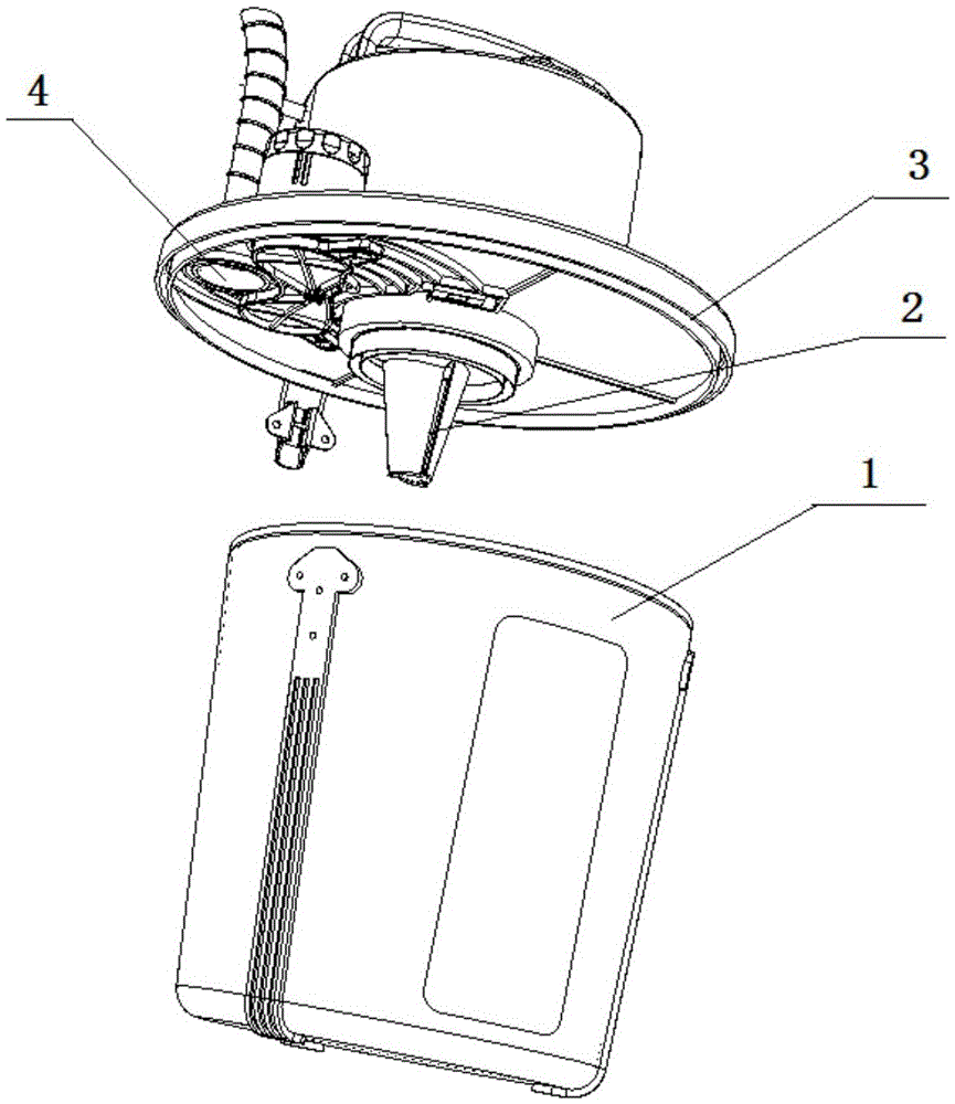
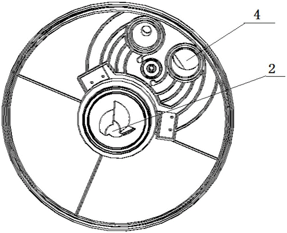
[0019] see Figure 1 to Figure 2 . It should be noted that the structures, proportions, sizes, etc. shown in the drawings attached to this specification are only used to match the content disclosed in the specification, for those who are familiar with this technology to understand and read, and are not used to limit the implementation of the present invention. Limiting conditions, so there is no technical substantive meaning, any modification of structure, change of proportional relationship or adjustment of size, without affecting the effect and purpose of the present invention, should still fall within the scope of the present invention. within the scope covered by the disclosed technical content. At the same ti...


PUM


Abstract

The invention provides a suction structure and a suction method for an air suction device of a sewing machine. The air suction device comprises a dustbin storing waste materials. The top cover of the dustbin is provided with an air inlet and a suction outlet. The exhaust inlet is communicated with an air suction motor. The dustbin is internally provided with a spiral air suction channel communicated with the suction outlet. The spiral air suction channel is used to make spiral airflow form in the dustbin under the suction forces of the air suction motor, so as to form a strong negative pressure region, and make the air inlet of the dustbin have very strong suction forces. Under the condition that the power of the air suction motor is not changed, the strongest air suction effect is achieved.

Description

technical field [0001] The invention relates to an air suction device for a sewing machine, in particular to an air suction structure and an air suction method of the air suction device for a sewing machine. Background technique [0002] The suction device is one of the most important additional devices in the sewing machine, which is mainly used to collect impurities such as thread ends and rags. At present, the air suction device is divided into two categories, one is a pneumatic air suction device coordinated with an external air source, and the other is an electric air suction device driven by a motor. The existing air suction device sucks air in a vertical way, the suction is small, the air displacement is small, and the suction efficiency is low. If you want to increase the suction and air displacement, you must increase the motor power, which will bring the motor cost and power consumption. amount increased. [0003] Chinese patent 201510298016.X discloses a dust co...

Claims


Application Information

Patent Timeline
Patent Type & Authority Applications(China)
IPC IPC(8): D05B81/00B08B15/04
CPCD05B81/00B08B15/04D05D2207/04
Inventor 李创陈勇智符志诚徐永明
Owner JACK SEWING MASCH CO LTD
Why Eureka
Try Eureka