Combined filling unit based on modularization

A modular and filling technology, applied in the direction of threaded bottle caps, etc., can solve the problems of poor structural strength, inconvenient processing and circulation, and few reusable parts, so as to achieve the effect of improving design and high market application value

Pending Publication Date: 2021-11-26
HEFEI ZHONGCHEN LIGHT IND MACHINERY
View PDF8 Cites 0 Cited by
  • Summary
  • Abstract
  • Description
  • Claims
  • Application Information

AI Technical Summary

Problems solved by technology

[0002] The design of the existing filling unit is to determine the composition, such as two-line filling and capping or three-line rinsing, filling and capping, and then do scheme design, drawing design, etc. This method not only has a long design period, but also has different The model has few reusable parts, which is not conducive to batch processing, resultin

Method used


Image

  • Combined filling unit based on modularization
  • Combined filling unit based on modularization
  • Combined filling unit based on modularization

Examples


Example Embodiment

[0026] Specific embodiment one:

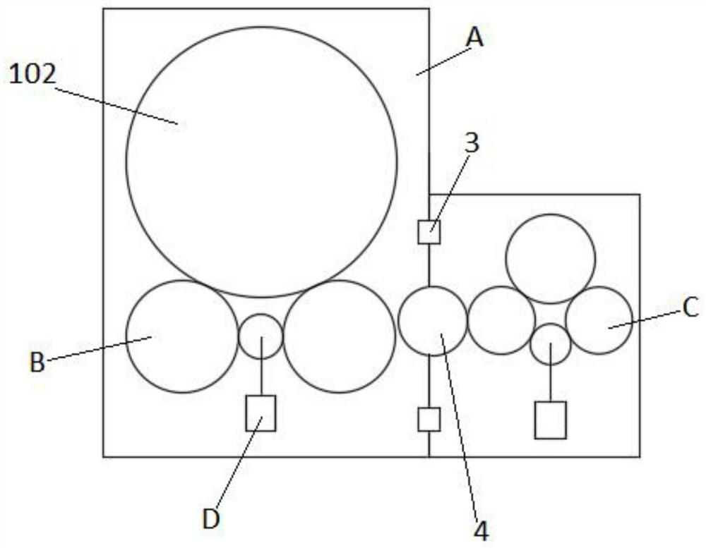
[0027] see figure 1 As shown, the present invention is a combination filling unit based on modularization, including a first functional module 1 and a second functional module 2 arranged side by side; the first functional module 1 includes a filling unit 102; the second functional module 2 Including a capping unit 201 or a capping unit 202; the filling unit 102, the capping unit 201 and the capping unit 202 all include a frame A, a bottle-in star wheel B, a bottle-out star wheel C and a drive Component D; the driving component D is composed of a drive motor and a conventional reducer in the field; the filling unit 102 is connected to the capping unit 201 or the capping unit 202 through a pair of positioning parts 3, and the filling unit 102 and the rotary The capping unit 201 or the capping unit 202 is connected through a transition star wheel 4; the filling unit 102 also includes a conventional filling mechanism in this field; the capping un...

Example Embodiment

[0029] Specific embodiment two:

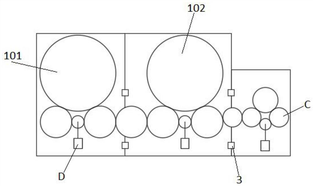
[0030] see figure 2As shown, the present invention is a combination filling unit based on modularization, including a first functional module 1 and a second functional module 2 arranged side by side; the first functional module 1 includes a bottle rinsing unit 101 and a filling unit 102 The second functional module 2 includes a capping unit 201 or a capping unit 202; the bottle rinsing unit 101, the filling unit 102, the capping unit 201 and the capping unit 202 all include a frame A, a star wheel for entering bottles B, a bottle-out star wheel C and a drive assembly D; the drive assembly D is composed of a drive motor and a conventional reducer in the field; between the bottle rinsing unit 101 and the filling unit 102 and between the filling unit 102 and the capping unit 201 Or the capping units 202 are respectively connected by a pair of positioning parts 3, and a transition The star wheel 4 is transmission connected; the bottle rinsing u...

Example Embodiment

[0032] Specific embodiment three:

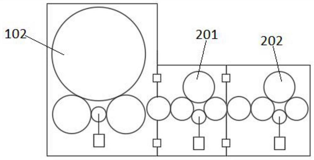
[0033] see image 3 As shown, the present invention is a combination filling unit based on modularization, including a first functional module 1 and a second functional module 2 arranged side by side; the first functional module 1 includes a filling unit 102; the second functional module 2 It includes a capping unit 201 and a capping unit 202; the filling unit 102, the capping unit 201 and the capping unit 202 all include a frame A, a bottle-in star wheel B, a bottle-out star wheel C and a drive Component D; the drive component D is composed of a drive motor and a conventional reducer in the field; the filling unit 102 and the capping unit 201 and the capping unit 201 and the capping unit 202 are respectively connected by a pair of positioning parts 3 , and between the filling unit 102 and the capping unit 201 and between the capping unit 201 and the capping unit 202 are respectively connected by a transition star wheel 4; the filling unit ...


PUM


Abstract

The invention discloses a combined filling unit based on modularization, and relates to the technical field of filling equipment. The combined filling unit comprises a first function module and a second function module which are arranged side by side, the first functional module comprises at least one bottle flushing unit and/or at least one filling unit, the second function module comprises at least one cap screwing unit and/or at least one cap pressing unit, and the bottle flushing units, the filling units, the cap screwing units and the cap pressing units all comprise racks, bottle feeding star wheels, bottle discharging star wheels and driving assemblies. According to the combined filling unit, based on the modular design, the design, manufacturing and circulation efficiency and the transportation convenience can be effectively improved, and the higher market application value is achieved.

Description

technical field [0001] The invention belongs to the technical field of filling equipment, in particular to a modularized combined filling unit. Background technique [0002] The design of the existing filling unit is to determine the composition, such as two-line filling and capping or three-line rinsing, filling and capping, and then do scheme design, drawing design, etc. This method not only has a long design period, but also has different The model has few reusable parts, which is not conducive to batch processing, resulting in low overall efficiency, and there is room for further improvement in quality control and cost control. On the other hand, in the case of multiple machines, the frame size of the overall design is relatively large, and there are problems such as poor structural strength, inconvenient processing and circulation, and inconvenient transportation of the whole machine. Therefore, it is urgent to study a modular-based combined filling unit in order to so...

Claims


Application Information

Patent Timeline
IPC IPC(8): B67B3/20
CPCB67B3/20
Inventor 郑长发张科周波
Owner HEFEI ZHONGCHEN LIGHT IND MACHINERY
Why Eureka
Try Eureka