
Beehive

Pending Publication Date: 2021-08-26
WARING MARK
View PDF0 Cites 1 Cited by
  • Summary
  • Abstract
  • Description
  • Claims
  • Application Information

AI Technical Summary

Benefits of technology

The current invention is an improved beehive design that allows bees to follow their natural instincts and reduces stress and physical damage to the colony. It features a natural moisture control system and a self-contained frame hanging system for inspection and harvesting of honeycomb. The unique hive body angle allows for a longer and more stable honeycomb compared to similar designs. The current design also does not require supers and reduces contamination from mites and pathogens.

Problems solved by technology

Drawbacks of horizontal box designs such as those of Langstroth and Wane include low air flow or dead air in the corners of the boxes.
Mitigation requires ventilation holes which can have a negative impact on the bees' ability to regulate the brood's temperature.
Also, moisture produced from the colony rises and collects at the roof, condenses, and then rains back down on the colony.
However, creation of the propolis requires excess expenditure of energy and hive resources.
The propolis also makes separation of the frames more difficult for the beekeeper, which in turn, places more stress on the colony.
Failure to control the moisture ultimately results in mold, mildew, and continuous damp, which compromises the colony's health and resilience.
Other drawbacks of the Langstroth design include box weight, and the square frame designs.
Also, the long straight frames and 90-degree angles of the design don't provide a natural starting point from which the bees can begin building.
Wax or plastic foundations and barriers have been added to the frames to address this issue, however, these solutions tend to just further restrict airflow and create additional health risks for the colony.
Because bees must continually move over the internal nest to get around the barriers, cross contamination in the form of mites, other invasive species and even environmental pesticides infusing in the foundation wax can poison the nest.
In addition to having to deal with the excess propolis as previously mentioned, removal of the frames leads to “rolling” of the bees.
As a frame is removed, any bees still on the structure of the frame will be scraped off by the other static frames and structures, damaging or killing the bees, which naturally causes defensive actions from the other bees.
Swarming and aggressiveness causes additional stress on the hive.
There is also always a risk that the queen will be killed during frame removal.
A major drawback of this design lies in the fact that the combs are prone to breaking off from the inadequate single attachment point during extraction from the hive.
Cross combing construction is also a problem with this design.
It also makes the beekeepers management and harvesting of the combs more difficult.
Often, it will lead to loss of the entire comb if not caught in early stages of formation.
There are numerous passages for the bees throughout the comb frames which reduces the likelihood of forager bees encountering house bees.
However, the complexity of the design, its construction, and management of the passage and ventilation system requires the beekeeper to stay on top of all adjustments in order to maintain control of moisture and brood temperature issues.
As such, the cost and complication of the system requires extensive knowledge and additional time and labor of the beekeeper.
None of the previously described designs have fully addressed the issue of rain, snow and other forms of precipitation from sitting on top of the hives.

Method used


Image

  • Beehive
  • Beehive
  • Beehive

Examples


Embodiment Construction

[0020]Following are detailed description of preferred embodiments, which are meant to be descriptive and not limiting.

[0021]The invention is an improved beehive.

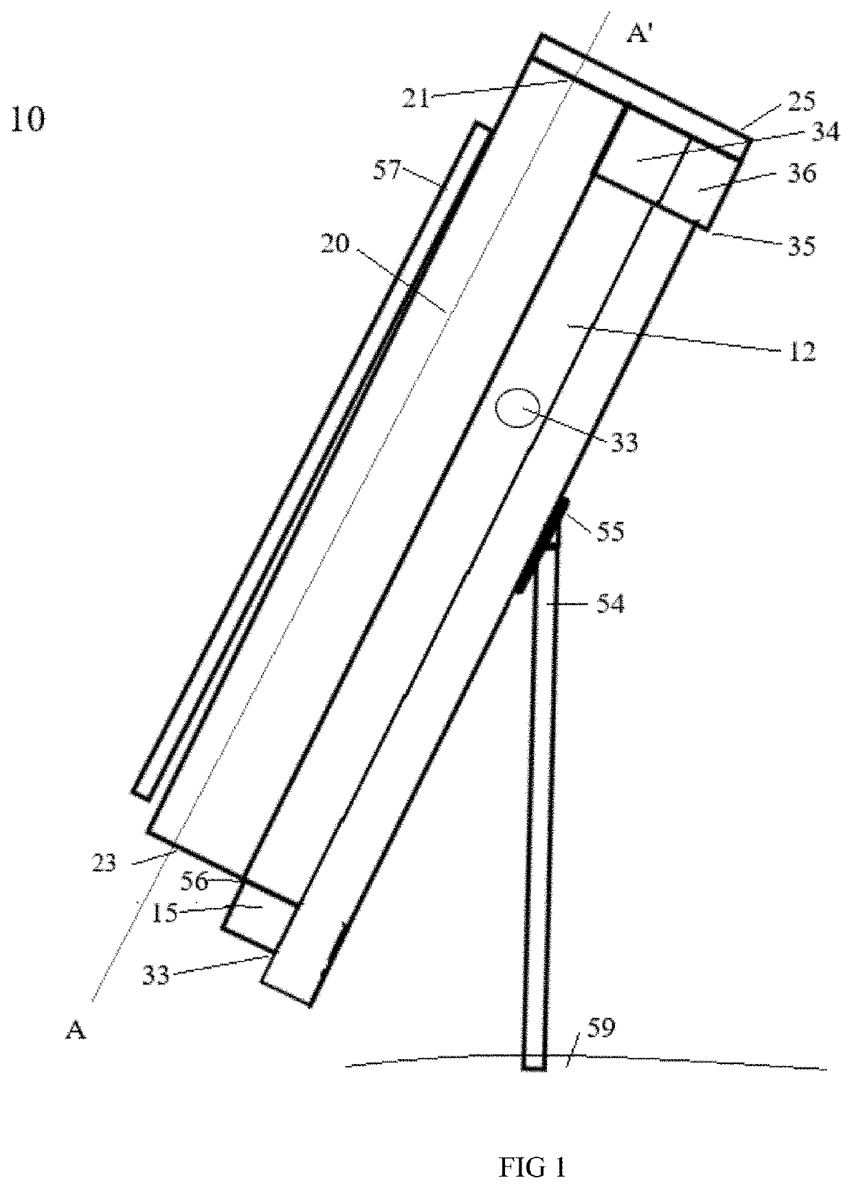
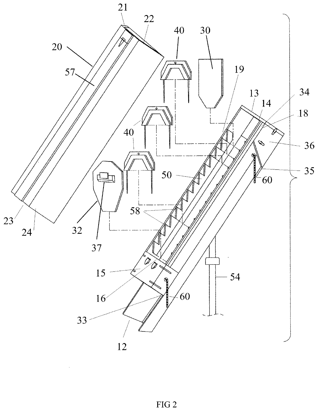
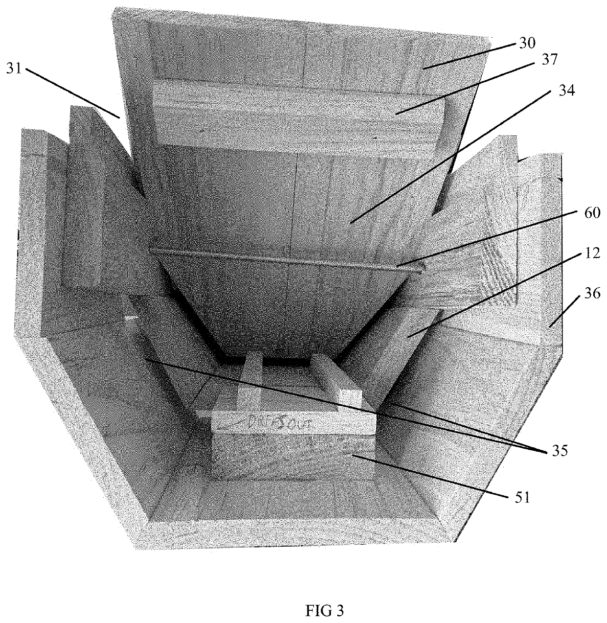
[0022]As shown in FIG. 1, the invention includes a beehive 10 comprising a hive box 12, a hive cover 20, a support post 54 (which can be typically attached to the hive box with an angled support 55) which can be disposed in the ground 59 at an angle. One or more bee entries 33 are located in the hive box. The hive cover 20 can include a first high cover end, or upper end, 21, a second high cover end, or lower end, 23, and, optionally, a roof plate 25 and / or a cover support leg 57. The hive box 12, includes a second hive box end, or lower end 15. Typically, the hive cover 20 will be attached to the hive box lower end 15 with a hive cover hinge 56. Preferably, as the hive cover 20 opens to expose the interior of the hive box 12, the cover support leg 57 will swing out and meet the ground 59. At the upper end of the hive box is...


PUM


Abstract

The current invention provides an improved yet simpler beehive design that addresses the shortcoming of previous designs while facilitating the ability of bees to follow their natural instincts. If features a natural moisture control system, facilitated by roof placement and framing configuration, and a self-contained frame hanging system for inspection of the broods' nest and harvesting of the honeycomb that minimizes physical damage to bees and the stress placed on the colony by those activities.

Description

RELATED APPLICATION[0001]This application claims the benefit of U.S. Provisional Application No. 62 / 978,519, filed on Feb. 19, 2020. The entire teachings of the above application are incorporated herein by reference.BACKGROUND OF THE INVENTION[0002]Domestic beekeeping has been practiced world-wide for centuries with the primary purposes being production of honey and wax, and pollination of crops. Most recently, more focus has shifted to pollination due to statistically significant increases in beehive mortality. Experts have attributed these increases to the introduction of parasites and diseases into the bee colonies.[0003]Common commercially available domestic beehives are known in the art as Langstroth, Warre, Kenya, and Cathedral hives. Each design has its own unique attributes and drawbacks.[0004]The Langstroth design, which has been around since the 1850s and is the most common design used in commercial honey production, consists of rectangular boxes of varying heights which c...

Claims


Application Information

Patent Timeline
IPC IPC(8): A01K47/02A01K47/06
CPCA01K47/02A01K47/06
Inventor WARING, MARK
Owner WARING MARK
Learn More