Gasification furnace burner deflection angle measuring device and method
A technology of deflection angle and measuring device, which is applied in the details of gasification device, the gasification of granular/powder fuel, and the manufacture of combustible gas, etc. The effect of high accuracy, improved performance, and simple operation
- Summary
- Abstract
- Description
- Claims
- Application Information
AI Technical Summary
Problems solved by technology
Method used
Image
Examples
Embodiment 1
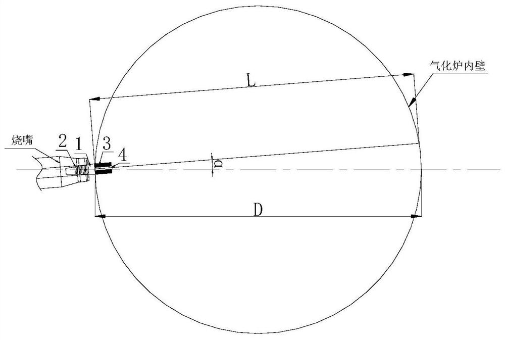
[0032] This embodiment provides a gasifier burner deflection angle measuring device, such as figure 1 As shown, the measuring device includes a mounting base 1, a base 3 and a rangefinder 4, and one end of the mounting base 1 is provided with a rangefinder 4, and the rangefinder 4 is connected to the mounting base 1 through the base 3, and the rangefinder 4 is preferably It is a laser range finder or an infrared range finder. The distance measuring line of the range finder 4 coincides with the axis of the central tube of the gasifier burner and the central axis of the mounting seat 1. The material of the mounting seat 1 and the base 3 is copper or Stainless steel, and between the rangefinder 4 and the base 3, as well as between the base 3 and the mounting base 1, are threaded. The base 3 is a cylindrical structure, which is convenient to connect with the mounting base 1. The other end of the mounting base 1 is a truncated cone The structure is used for inserting into the centr...
Embodiment 2
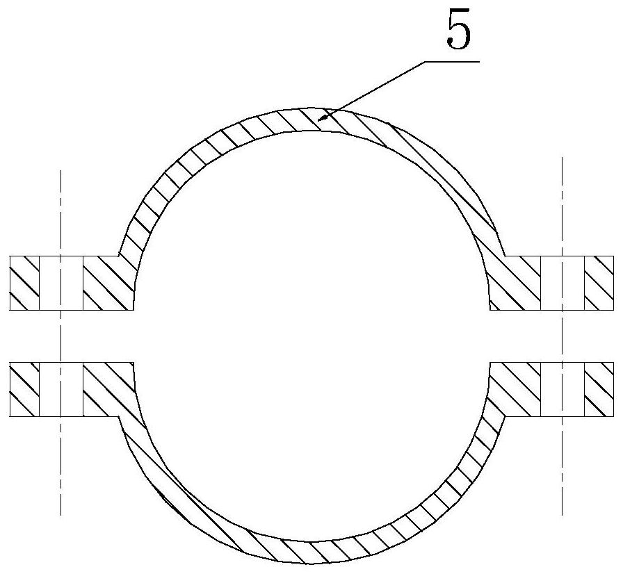
[0035] On the basis of Embodiment 1, wherein, the outer wall of the mounting base 1 is provided with several scale lines 2, the scale lines 2 are circular scale lines, and the center of circle corresponding to each scale line 2 is located on the axis of the mounting base 1, and the scale lines 2 are Groove design, a buckle 5 is installed on the outer periphery of the scale line 2, the buckle 5 includes two semi-annular structures, and the ends of the two semi-annular structures are provided with fixing parts for locking the buckle 5, such as image 3 As shown, the inner wall of the buckle 5 is provided with a protrusion engaged with the groove of the scale line 2, which makes it easier to fix the buckle 5 on the scale line 2. During installation, fix the buckle 5 at the scale line 2 of the larger size, and gradually adjust the position of the buckle 5 when the mounting base 1 is inserted into the center tube of the gasifier burner, and finally pass through the gasifier burner ...
Embodiment 3
[0037] Based on the device for measuring the deflection angle of the gasifier burner in Embodiment 1, Embodiment 3 of the present invention also provides a measurement method for the above-mentioned measuring device, including the following steps:
[0038] Step 1: Insert the mounting base 1 into the central tube of the gasifier burner, and adjust the position of the mounting base 1 so that the scale line 2 on the outer wall of the mounting base 1 is parallel to or coincident with the end of the central tube of the gasifier burner , so that the distance measuring line of the range finder 4 coincides with the axis of the mounting base 1 and the axis of the central tube of the gasifier burner, such as figure 2 shown;
[0039] Step 2: The range finder 4 adopts a laser range finder, and the laser beam emitted by the laser range finder is reflected by the inner wall of the gasification furnace and then enters the laser range finder, and the laser range finder calculates according to ...
PUM
 Abstract
Description
Claims
Application Information
 - R&D
- Intellectual Property
- Life Sciences
- Materials
- Tech Scout
- Unparalleled Data Quality
- Higher Quality Content
- 60% Fewer Hallucinations
Browse by: Latest US Patents, China's latest patents, Technical Efficacy Thesaurus, Application Domain, Technology Topic, Popular Technical Reports.
© 2025 PatSnap. All rights reserved.Legal|Privacy policy|Modern Slavery Act Transparency Statement|Sitemap|About US| Contact US: help@patsnap.com


