A transmission temperature oil level thermostat using a magnetically encoded angular displacement chip

A magnetic coding and angular displacement technology, applied in the field of transmission temperature oil surface thermostat, can solve the problem of easy deviation of detection results, and achieve the effect of improving cooling effect, expanding detection range, and speeding up flow speed.

Active Publication Date: 2022-05-13
福建省力得自动化设备有限公司
View PDF17 Cites 0 Cited by
  • Summary
  • Abstract
  • Description
  • Claims
  • Application Information

AI Technical Summary

Problems solved by technology

[0004] The purpose of the present invention is to provide a transmission temperature oil surface thermostat using a magnetically encoded angular displacement chip, which has the advantage of a large monitoring range and solves the problem that the detection results are prone to deviations in the prior art

Method used


Image

  • A transmission temperature oil level thermostat using a magnetically encoded angular displacement chip
  • A transmission temperature oil level thermostat using a magnetically encoded angular displacement chip
  • A transmission temperature oil level thermostat using a magnetically encoded angular displacement chip

Examples


Embodiment 1

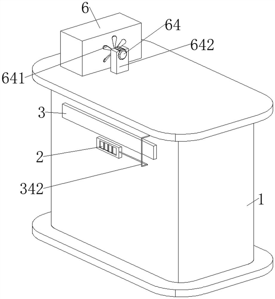
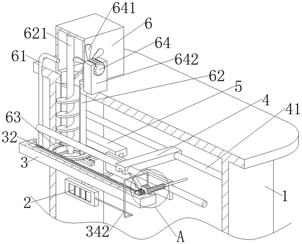
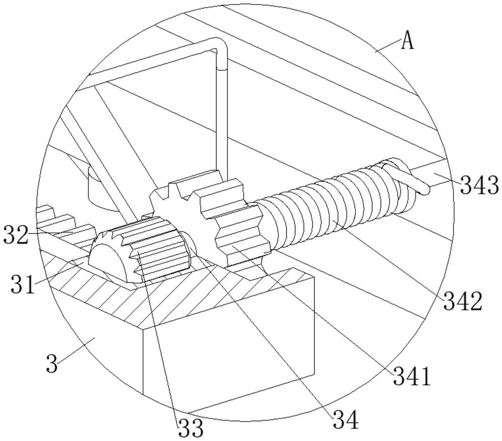
[0027] refer to Figure 1-Figure 4 , the present invention provides a technical solution: a transmission temperature oil level thermostat using a magnetically encoded angular displacement chip, including a transformer box 1 with built-in transformer oil and a magnetically encoded motor 33, and the outer wall of the transformer box 1 is fixedly connected with The temperature controller main body 2 is fixedly connected with the installation bar 3 on the transformer box 1, and the installation block 31 is slidably connected with the installation bar 3. There is a cavity for the installation of the magnetic encoding motor 33 in the installation block 31, and the output of the magnetic encoding motor 33 One end is fixedly connected with a rotating shaft 34, the rotating shaft 34 is coaxially fixedly connected with a first gear 341, the mounting bar 3 is provided with teeth 32 meshing with the first gear 341, and the end of the rotating shaft 34 away from the first gear 341 is coaxia...

Embodiment 2

[0040] refer to Figure 9 , is basically the same as Embodiment 1, the difference is that the drive mechanism includes a rack 72, the rack 72 is fixedly connected to the second slider 51, and the screw pump shaft 621 is fixedly connected with a one-way bearing 71, and the one-way bearing 71 The second gear ring 7 is fixedly connected to the top, the second gear ring 7 is located on the same axis as the screw pump shaft 621 , and the rack gear 72 meshes with the second gear ring 7 .

[0041] When the second slider 51 slides, the rack 72 fixedly connected to the second slider 51 slides synchronously. Since the rack 72 meshes with the second ring gear 7, the rack 72 that slides back and forth can drive the second ring gear 7. Reciprocating rotation, due to the setting of the one-way bearing 71, the second gear ring 7 can only rotate in one direction on the screw pump shaft 621, so that the second gear ring 7 that rotates when the second gear ring 7 rotates on the screw pump shaft...


PUM


Abstract

The invention discloses a transmission temperature oil level thermostat using a magnetically encoded angular displacement chip, which belongs to the field of electric equipment. A transmission temperature oil level thermostat using a magnetically encoded angular displacement chip includes a transformer with built-in transformer oil Box and magnetically encoded motor. There is a cavity for the magnetically encoded motor to be installed in the installation block. The end of the wire away from the probe runs through the transformer box and extends to its outside to be fixedly connected to the main body of the temperature controller. In the present invention, by setting the installation block and the first gear, the probe can move in the transformer box to detect the temperature of the transformer oil, which expands the detection range and improves the detection accuracy. Disturb the flow to make the transformer oil absorb heat evenly. Through the cooperation of the cooling mechanism and the driving mechanism, the flow speed of the transformer oil in the transformer box is accelerated, and the cooling effect is improved.

Description

technical field [0001] The invention relates to the technical field of power system equipment, in particular to a transmission temperature oil level thermostat using a magnetically encoded angular displacement chip. Background technique [0002] The oil level thermostat for transformers is designed to measure and control the oil temperature of large transformers. It is also suitable for temperature detection and control of other equipment. The oil level thermostat for transformers can monitor the temperature of transformer oil when it is in use. In this way, real-time monitoring of transformer operation can be realized. [0003] However, because the probes of the existing temperature controllers are fixed during use, the range of detection is relatively small, so that the detection results are deviated. Contents of the invention [0004] The purpose of the present invention is to provide a transmission temperature oil level thermostat using a magnetically encoded angular ...

Claims


Application Information

Patent Timeline
Patent Type & Authority Patents(China)
IPC IPC(8): G05D23/19
CPCG05D23/1931
Inventor 王桓刘锦锋
Owner 福建省力得自动化设备有限公司
Why Eureka
Try Eureka