Visual line connector upper pile head insulation cover and installation method
An insulating cover and linker technology, applied in the manufacture of emergency protection devices, circuits, fuses, etc., can solve problems such as ground faults and short-circuit accidents, threats to the safe, stable and reliable operation of overhead lines, and achieve deflection prevention, rapid installation, and increased insulation effect of space
- Summary
- Abstract
- Description
- Claims
- Application Information
AI Technical Summary
Problems solved by technology
Method used
Image

Examples
Embodiment 1
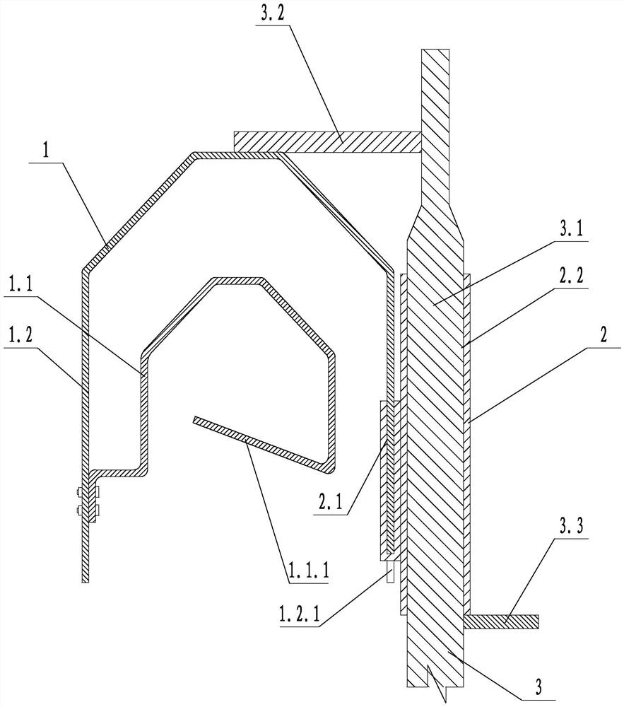
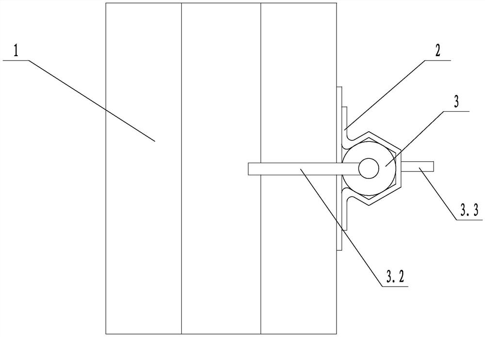
[0027] Such as figure 1 and figure 2 As shown in the figure, a visual insulating cover for pile heads includes a transparent insulating cover 1, a mounting splint 2 and a mounting rod 3. The transparent insulating cover 1 includes an inner clamping shell 1.1 and an outer protective cover 1.2, and the inner clamping shell 1.1 is all Set in the outer protective cover 1.2. The section of the inner clamping shell 1.1 is an inverted U-shape, one side of the inner clamping shell 1.1 is fixed with the outer protective cover 1.2, and the other side of the inner clamping shell 1.1 is provided with a limiting plate facing the inner side of the U-shape 1.1.1, the free end of the limiting plate 1.1.1 is set obliquely upward. The mounting splint 2 is provided with an upward opening slot 2.1 and a vertical clamping hole 2.2. The upper end of the mounting rod 3 is provided with a clamping part 3.1, and the side wall of the clamping part 3.1 is provided with a limit rod 3.2. The lower end...
Embodiment 2
[0030] Such as figure 1 and figure 2As shown, on the basis of Embodiment 1, the installation rod 3 is provided with a lower stop rod 3.3, the lower stop rod 3.3 is perpendicular to the installation rod 3, the lower stop rod 3.3 is arranged below the clamping part 3.1, and the lower stop rod 3.3 Contact with the lower end of the clamping part 3.1. The lower stop bar 3.3 is threadedly connected with the installation bar 3 . The structure can prevent the installation splint 2 from sliding up and down relative to the installation rod 3 during installation.
Embodiment 3
[0032] A method for installing an insulating cover on a pile head with visualization, using the above-mentioned insulation cover on a pile head with visualization, including the following steps:
[0033] a. Insulation cover assembly: pass the clamping part 3.1 of the installation rod 3 through the clamping hole 2.2 of the installation splint 2, so that the clamping hole 2.2 utilizes its own elasticity and the tight fit between the clamping hole 2.2 and the clamping part 3.1 Clamp the clamping part 3.1, clamp the clamping part 3.1 with the clamping hole 2.2, make the limit rod 3.2 contact the upper end of the outer protective cover 1.2 at the same time, and then snap the lower end of the side plate of the outer protective cover 1.2 downward into the opening slot 2.1;
[0034] b. Insulation cover installation: move the transparent insulation cover 1 to the installation position through the installation rod 3, and snap the inner clamping shell 1.1 into the ring from top to bottom...
PUM
 Abstract
Description
Claims
Application Information
 - R&D Engineer
- R&D Manager
- IP Professional
- Industry Leading Data Capabilities
- Powerful AI technology
- Patent DNA Extraction
Browse by: Latest US Patents, China's latest patents, Technical Efficacy Thesaurus, Application Domain, Technology Topic.
© 2024 PatSnap. All rights reserved.Legal|Privacy policy|Modern Slavery Act Transparency Statement|Sitemap