Portable vehicle-mounted network communication equipment

A technology for in-vehicle network and communication equipment, applied in the field of network communication, can solve problems such as rainwater corrosion and damage to signal receiving equipment, and achieve the effects of sensitive triggering, loss reduction, and cumbersome operations.

Active Publication Date: 2021-11-26
南通儒佳网络科技有限公司
View PDF5 Cites 0 Cited by
  • Summary
  • Abstract
  • Description
  • Claims
  • Application Information

AI Technical Summary

Problems solved by technology

[0006] In order to make up for the deficiencies of the existing technology and solve the problem that the vehicle-mounted network communication receiving equipment is usually installed on the roof and exposed to the open air for a long time, it is easily corroded by rainwater and causes damage to the signal receiving equipment to a certain extent. A portable vehicle network communication device

Method used


Image

  • Portable vehicle-mounted network communication equipment
  • Portable vehicle-mounted network communication equipment
  • Portable vehicle-mounted network communication equipment

Examples


Embodiment 1

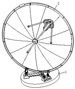
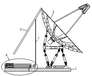
[0031] Such as Figure 1 to Figure 6 As shown, a portable vehicle-mounted network communication device according to the present invention includes a base 1, and the base 1 is installed on the roof; a signal receiver 2 is installed on the upper side of the base 1; the top of the signal receiver 2 passes through The torsion spring is hinged with a baffle 3; the upper side of the base 1 is fixedly connected with a control block 4; the control block 4 is provided with a mounting groove 5; the mounting groove 5 is provided with a telescopic assembly; the upper side of the base 1 The position close to the opening end of the installation groove 5 is connected with the guide wheel 6 through the rotation of the bracket; the lower side of the baffle plate 3 is fixedly connected with a connecting rope 7, and the other end of the connecting rope 7 bypasses the guide wheel 6 and is fixedly connected with the telescopic assembly; normal In this state, the connecting rope 7 is in a tight sta...

Embodiment 2

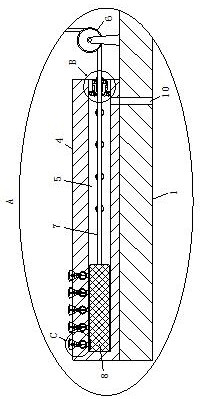
[0040] Such as Figure 7 As shown in Comparative Example 1, as another embodiment of the present invention, the elastic element 13 is a hollow structure, and the elastic element 13 is filled with lubricating oil; Holes 28; the combined ring 11 is provided with a filling hole 29 near the position of the elastic element 13, and the filling hole 29 communicates with the elastic element 13; a one-way valve is installed in the filling hole 29; the movable ring 12 is combined When the ring 11 rotates and moves inside, the elastic element 13 will be elongated and twisted, and then the lubricating oil inside the elastic element 13 will be squeezed and sprayed out through the through hole 28, sprayed in the spiral groove inside the coupling ring 11, for subsequent Combining the relative rotation between the ring 11 and the movable ring 12 to provide a lubricating effect, avoiding the problem that the movable ring 12 cannot rotate due to excessive friction. Lubricating oil is supplemen...


PUM


Abstract

The invention belongs to the technical field of network communication, and particularly relates to portable vehicle-mounted network communication equipment which comprises a base; a signal receiver is mounted on the upper side of the base; a baffle is hinged to the top of the signal receiver through a torsional spring; a control block is fixedly connected to the upper side of the base; a mounting groove is formed in the control block; a telescopic assembly is arranged in the mounting groove; the upper side of the base is rotationally connected with a guide wheel through a support. The lower side of the baffle is fixedly connected with a connecting rope, and the other end of the connecting rope bypasses the guide wheel and is fixedly connected with the telescopic assembly. In rainy days, the telescopic assembly is manually started to loosen the connecting rope, and then under the action of the torsional spring, the baffle rotates to the position above the signal receiver and shields the signal receiver, so that the effect of shielding the signal receiver from rain is achieved, and the problem that the network communication equipment is corroded and damaged due to the fact that the network communication equipment is exposed in rainwater for a long time is avoided, unnecessary loss is reduced, and it is ensured that normal working performance can be maintained subsequently.

Description

technical field [0001] The invention belongs to the technical field of network communication, in particular to a portable vehicle network communication device. Background technique [0002] A TV OB van is a car equipped with network communication equipment, which uses network communication equipment to send signals to TV stations for live broadcast. The TV OB van is a vehicle-mounted small "television station" with the characteristics of maneuverability and wide range of activities. It can conduct on-site video recording and on-site editing away from the TV center, and can transmit the recorded programs to the TV center in real time for on-site broadcast. . [0003] There are also some technical solutions about network communication equipment in the prior art. For example, a Chinese patent with application number 2011101416453 discloses network communication equipment, including a voltage detection circuit, a charging and discharging circuit, a power supply circuit, a centr...

Claims


Application Information

Patent Timeline
Patent Type & Authority Applications(China)
IPC IPC(8): H04B1/3888H04B1/3822H04Q1/02
CPCH04B1/3888H04B1/3822H04Q1/11H04Q1/114
Inventor 刘俊儒
Owner 南通儒佳网络科技有限公司
Why Eureka
Try Eureka