A portable vehicle network communication device

A technology for in-vehicle network and communication equipment, applied in the field of network communication, can solve problems such as rainwater corrosion and damage to signal receiving equipment, and achieve the effects of sensitive triggering, loss reduction, and cumbersome operations.

Active Publication Date: 2022-02-08
南通儒佳网络科技有限公司
View PDF5 Cites 0 Cited by
  • Summary
  • Abstract
  • Description
  • Claims
  • Application Information

AI Technical Summary

Problems solved by technology

[0006] In order to make up for the deficiencies of the existing technology and solve the problem that the vehicle-mounted network communication receiving equipment is usually installed on the roof and exposed to the open air for a long time, it is easily corroded by rainwater and causes damage to the signal receiving equipment to a certain extent. A portable vehicle network communication device

Method used


Image

  • A portable vehicle network communication device
  • A portable vehicle network communication device
  • A portable vehicle network communication device

Examples


Embodiment 1

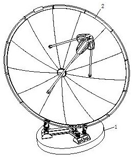
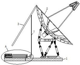
[0031] like Figure 1 to 6 Illustrated, a portable vehicle network communication device according to the present invention includes a base 1, and the base 1 is mounted on a roof; 1 the upper side of the base 2 is attached to a signal receiver; the signal receiver 2 through the top the torsion spring is hinged flap 3; the upper side of the fixed base 1 with a control block 4; the control block 4 defines a mounting groove 5; 5 of the mounting groove is provided in the telescopic assembly; the upper side of the base 1 near the mounting position of the open end of the slot 5 is rotatably connected by a bracket with a guide wheel 6; the lower side of the baffle plate 3 is fixed to a connecting cable 7, and is connected to the other end of the rope 7 and the bypass guide wheel 6 fixed to the telescopic assembly; normal rope 7 is connected to the shutter 3 and the state of tension stretched state, in case of rainy weather, the telescoping assembly by manually starting rope 7 is connected ...

Embodiment 2

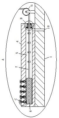
[0040] like Figure 7 As shown in Comparative Example a, as another embodiment of the invention, the elastic member 13 is a hollow structure, and the elastic member 13 is filled with lubricating oil; a position close to the spiral groove 13 the elastic element defines a through- bore 28; the coupling ring 11 near the position of the elastic member 13 defines a feed hole 29 and feed hole 29 communicating with the resilient member 13; the feed hole 29 is mounted a check valve; ring 12 in binding activity when the inner ring 11 is rotated will move the elastic member 13 stretched and twisted, and thus the lubricating oil 13 inside the resilient member is compressed and discharged outside through the through hole 28, the interior of the spray ring 11 in conjunction with a helical groove, for subsequent binding activity between the ring 12 and the ring 11 to provide lubrication effect relative rotation, the friction is too large to avoid problems movable ring 12 can not rotate, when the...


PUM


Abstract

The invention belongs to the technical field of network communication, and is specifically a portable vehicle-mounted network communication device, including a base; a signal receiver is installed on the upper side of the base; a baffle is hinged on the top of the signal receiver through a torsion spring; the A control block is fixedly connected to the upper side of the base; a mounting groove is opened in the control block; a telescopic assembly is arranged in the mounting groove; a guide wheel is connected to the upper side of the base through the rotation of the bracket; the lower side of the baffle is fixedly connected to There is a connecting rope, and the other end of the connecting rope bypasses the guide wheel and is fixedly connected to the telescopic component; in case of rainy weather, the connecting rope is loosened by manually starting the telescopic component, and then under the action of the torsion spring, the baffle rotates to the signal Above the receiver and cover the signal receiver, it has the effect of shielding the signal receiver from the rain, avoiding the long-term exposure of network communication equipment to rainwater, causing corrosion and damage to the equipment, reducing unnecessary losses, and ensuring its follow-up. Maintain normal working performance.

Description

Technical field [0001] The present invention belongs to the technical field of communication networks, specifically in-vehicle network is a portable communication device. Background technique [0002] TV truck is carrying communications equipment automotive network, using a network communication device sends a signal to TV for playback, for live broadcast. TV truck is a kind of flexible, large range of activities and other characteristics of a small car, "TV", which can be distanced from the TV center for live video, live editing, and can be instantly transmitted to the center of the recorded TV program, broadcast live . [0003] In the prior art there have been some technical program on a network communication device, such as a Chinese patent application No. 2011101416453 disclosed a network communication device, comprising a voltage detection circuit, the charge-discharge circuit, a power supply circuit, a central processing unit, the sub- system circuit, overheat detection cir...

Claims


Application Information

Patent Timeline
Patent Type & Authority Patents(China)
IPC IPC(8): H04B1/3888H04B1/3822H04Q1/02
CPCH04B1/3888H04B1/3822H04Q1/11H04Q1/114
Inventor 刘俊儒
Owner 南通儒佳网络科技有限公司
Why Eureka
Try Eureka