
Rotary industrial robot spraying shielding device and spraying shielding method thereof

A kind of industrial robot and rotary technology, applied in the direction of coating, manipulator, spraying device, etc., can solve the problems of reduced service life of baffle, unfavorable work efficiency, lifting, etc., and achieve the effect of improving efficiency

Inactive Publication Date: 2021-11-30
NANJING YUSHENG ROBOT CO LTD
View PDF0 Cites 0 Cited by
  • Summary
  • Abstract
  • Description
  • Claims
  • Application Information

AI Technical Summary

Problems solved by technology

[0002] When spraying paint, in order to achieve the limitation of the paint spraying range, avoid the outer area from being polluted by paint, and in order to achieve the spraying of specific patterns, it is often necessary to use a baffle to achieve the limit of the paint spraying boundary and make the paint spray The scope of spraying is artificially controllable. In the prior art, baffles are mostly used for nailing. After the spraying is completed, the baffles are disassembled. Therefore, the baffles used for the existing paint spraying shielding are repeated. In the process of assembly and disassembly, long-term use can easily reduce the service life of the baffle used, and the process of assembling and disassembling the baffle is more troublesome, which is not conducive to the improvement of work efficiency, especially for the finer spray patterns. When shading, it is necessary to cut the baffle, which will lead to an increase in the cost of spraying shading and a decrease in spraying efficiency. Therefore, a reusable method is proposed that can completely block the details of the pattern and reduce the preparation for spraying. The invested labor cost can effectively improve the spraying efficiency of the rotary industrial robot spraying shielding equipment to solve the above problems

Method used


Image

  • Rotary industrial robot spraying shielding device and spraying shielding method thereof
  • Rotary industrial robot spraying shielding device and spraying shielding method thereof
  • Rotary industrial robot spraying shielding device and spraying shielding method thereof

Examples


Embodiment 1

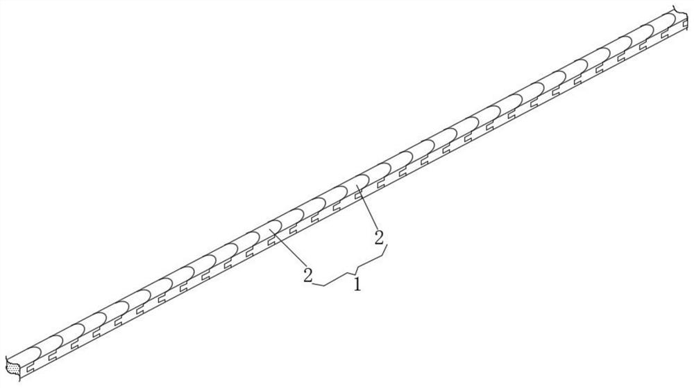
[0026] See Figure 1-3 This embodiment provides a rotary industrial robot spraying occlusion, including folding rod 1, folding rod 1 including a plurality of deflection block 2, and the folding rod 1 formed by assembling a plurality of deflection blocks 2 can be folded, so that it can be different The shape of the spray pattern is blocked, and the scope of the folding rod 1 blocks the spray coating.

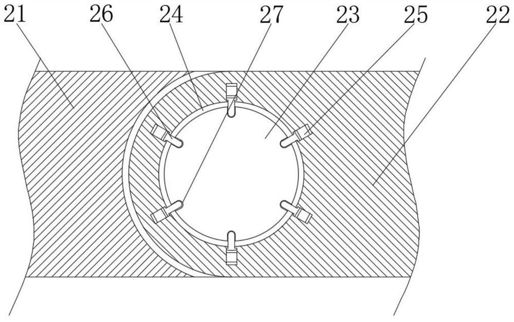
[0027] In order to achieve the relative deflection between the deflection block 2, one end of the deflection block 2 is provided with the mounting groove 21 of the U-shaped structure, and the deflection block 2 is disposed from one end of the mounting groove 21, and the mounting groove 21 and the mounting plate 22 match. The adjacent deflection blocks 2 are hinged between the mounting grooves 21 and the mounting plate 22, and the deflection block 2 is hinged together by the mounting groove 21 and the mounting plate 22, and the deflection block 2 can be relatively rotated, and then by ...

Embodiment 2

[0035] See Figure 4-5 Further improvements were made on the basis of Example 1: During the process of blocking the paint, since the size of the spray pattern cannot be achieved, it is necessary to modify the number of deflection block 2, that is, the deflection block 2 The number of increases and decreases.

[0036] The two ends of the deflection block 2 are separately opened, and the deflection block 2 is attached to the mounting groove 21 and the mounting plate 22, and the end portion of the mounting groove 21 is attached to the mounting groove 21, respectively. The end portion of the plate 22 is integrally provided with a plate 29 that matches the buckle groove 28, and is used by the mating between the plate 29 and the buckle groove 28, the mounting groove 21 and the mounting plate 22 can be implemented at the end portion of the deflection block 2. Disassembly and installation.

[0037] Among them, when the mounting groove 21 and the mounting plate 22 of the deflection block 2 ...

Embodiment 3

[0045] See Image 6 Further improvement is made in the basis of Example 2: A large metal material is present in the apparatus of the spray pattern, and the non-metallic material is fixed after the shape of the folded rod 1, and the support rod or bond is used to achieve the folding rod 1 and The fixation between the devices, but for the metal equipment, the effect of fixing the folding rod 1 and the device is better than the device.

[0046] The inside of the deflection block 2 is opened with a fixing chamber 4, and an electric suction cup 41 is mounted inside the fixing chamber 4, and the electric suction cup 41 uses the electromagnet in the prior art.

[0047] A iron plate 42 is fixed between the fixing chamber 4 and the deflection block 2, the iron plate 42 is separated from the electric suction cup 41 and is pair, the front panel of the iron plate 42 and the electrical chuck 41 is parallel to each other, wherein the iron plate 42 can convert the electric suction cup. The magnet...


PUM


Abstract

The invention discloses a rotary industrial robot spraying shielding device and a spraying shielding method thereof, and relates to the technical field of spraying shielding devices. The rotary industrial robot spraying shielding device comprises a folding rod, the folding rod comprises a plurality of deflection blocks, one end of each deflection block is provided with a mounting groove, a mounting plate is arranged at one end, away from the mounting groove, of each deflection block, and the mounting grooves are matched with the mounting plates. The adjacent deflection blocks are hinged through the mounting grooves and the mounting plates, connecting discs are fixed into the mounting grooves, connecting holes matched with the connecting discs are formed in the side faces of the mounting plates, telescopic rods are inserted into the telescopic holes, and electromagnets and permanent magnets are arranged between the ends of the telescopic rods and the inner walls, away from the opening ends, of the telescopic holes. Fixing holes matched with the telescopic rods are formed in the outer walls of the connecting discs. Through cooperative use of all the devices, spraying patterns can be completely shielded, cutting of a baffle is omitted so that the labor cost can be reduced, meanwhile, rapid matching between the baffle and the spraying patterns can be achieved, and improvement of the spraying efficiency is facilitated.

Description

Technical field [0001] The present invention relates to the technical field of spraying occlusion apparatus, and in particular, a rotary industrial robot spray occlusion occlusion occlusion and its spray occlusion method. Background technique [0002] When the paint spray is applied, in order to achieve a limitation of the paint spraying range, the outer region is avoided by paint contamination, and to be able to achieve a specific pattern, it is often necessary to use the baffle to achieve the definition of the oil paint spray boundary, so that the paint The spray range reaches human controllable purposes, in the prior art, multi-baffle is used to perform nailing, after the spray is completed, the baffle is disassembled, so the existing paint is sprayed obscured the baffle used, repeat The process of assembling and dismantling, long-term use is easy to reduce the life of the baffle used, and the process of baffle assembly and dismantling is more troublesome, which is not conduci...

Claims


Application Information

Patent Timeline
Patent Type & Authority Applications(China)
IPC IPC(8): B05B12/20B05D1/32B25J11/00
CPCB05B12/20B05D1/32B25J11/0075
Inventor 董阿朋殷毅荣
Owner NANJING YUSHENG ROBOT CO LTD
Learn More