Flanging equipment for core body of spiral-plate heat exchanger

A spiral plate and heat exchanger technology, applied in heat exchange equipment and other directions, can solve the problems of large axial force, large space size, and low efficiency of flanging sheet materials, and achieve a simple structure, easy implementation, and easy use Effect

Active Publication Date: 2021-11-30
ZHENHAI PETROCHEM JIANAN ENG
View PDF8 Cites 0 Cited by
  • Summary
  • Abstract
  • Description
  • Claims
  • Application Information

AI Technical Summary

Problems solved by technology

[0003] 1. The mold for spinning or stamping is large, and the space required is large, which cannot meet the flanging processing of small spacing and small space positions;
[0004] 2. The spinning method needs to be supported by an outer mold for the flanging process, which cannot realize the flanging work under the working conditions of multi-layer and small spacing;
[0005] 3. The existing flanging technology can realize circular or concentric flanging processing. For spiral tubular sheet materials, the mold needs to be replaced continuously, which cannot be processed continuously, and the efficiency is very low;
[0006] 4. During the flanging process of stamping forming, the axial force on the flanging sheet is too large, and there is a risk of axial displacement of the sheet

Method used


Image

  • Flanging equipment for core body of spiral-plate heat exchanger
  • Flanging equipment for core body of spiral-plate heat exchanger
  • Flanging equipment for core body of spiral-plate heat exchanger

Examples


Embodiment Construction

[0031] The present invention will be further described in detail below in conjunction with the accompanying drawings and embodiments.

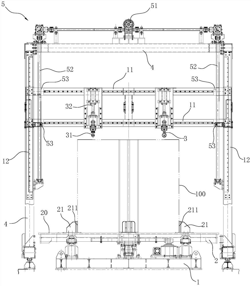
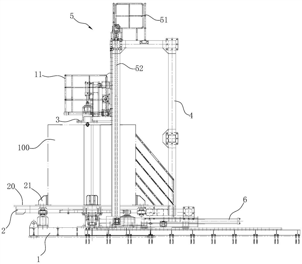
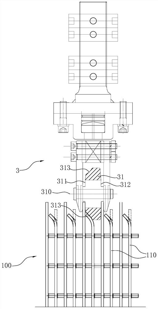
[0032] Such as Figure 1~3 As shown, it is a flanging device for the core of a spiral plate heat exchanger according to the present invention. The flanging device includes a base 1, a turntable 2, a flanging assembly 3, a frame 4, a first slide rail 11, The second sliding rail 12 , the second driving member (not shown in the figure), the third driving member 5 , and the fourth driving member 6 .

[0033] Wherein, the frame 4 is in the shape of a door, and the base 1 is arranged at the bottom center of the frame 4 , and the base 1 is arranged to move horizontally along the front and rear directions under the action of an external force, so as to enter and exit the frame 4 . The above-mentioned fourth driving member 6 is a hydraulic cylinder arranged horizontally, and its output end is connected with the base 1 to provide the above-mentioned ex...


PUM


Abstract

The invention discloses flanging equipment for a core body of a spiral-plate heat exchanger. The flanging equipment comprises a base (1), a turntable (2), a flanging assembly (3) and a second driving part, wherein the turntable (2) is rotationally arranged on the base, and the top surface of the turntable (2) is a supporting surface (20) allowing the core body (100) of the spiral-plate heat exchanger to be vertically placed and restrained on the turntable (2); the flanging assembly (3) is arranged above the turntable (2) in a horizontal moving manner and comprises a flanging wheel (31) and a first driving part (32), wherein the flanging wheel (31) can move up and down, is used for corresponding to the top end of a spiral plate (110) of the core body and is used for downwards flanging the top end of the spiral plate (110), and the output end of the first driving part (32) is connected with the flanging wheel (31) so as to drive the flanging wheel (31) to move up and down; and the second driving part acts on the flanging assembly (3) so as to drive the flanging assembly (3) to move horizontally. Compared with the prior art, the flanging equipment can be suitable for flanging of multi-layer spiral plates in a small-spacing and small-space range.

Description

technical field [0001] The invention belongs to the technical field of metal flanging, and in particular relates to a flanging device used for a core body of a spiral plate heat exchanger. Background technique [0002] Existing spiral plate flanging equipment is the disclosed structure of the utility model patent "spiral plate flanging device" (authorization announcement number is CN204148325U) such as the patent No. ZL201420505088. Positioning wheels, the first vertical plate has two pieces that are respectively arranged on the two ends of the base to stand oppositely, and positioning wheels are installed at both ends of the top of each first vertical plate, and the rotating shaft of the positioning wheel extends vertically. Two flanging wheels are arranged vertically in the middle position of the lower part. The rotating shaft of the flanging wheels is vertical to the first vertical plate. The flanging wheels are in the shape of a circular truncated cone. The wheel surfac...

Claims


Application Information

Patent Timeline
Patent Type & Authority Applications(China)
IPC IPC(8): B21D19/04B21D53/04
CPCB21D19/043B21D53/04
Inventor 都跃良忻红波李凌虞世君张永辉俞晓波
Owner ZHENHAI PETROCHEM JIANAN ENG
Why Eureka
Try Eureka