
Blowing nozzle

A technology of blowing nozzles and nozzle boxes, applied in the direction of injection devices, injection devices, liquid fuel engines, etc., to achieve the effect of simple mechanisms

Pending Publication Date: 2021-11-30
BRUECKNER MASCHB
View PDF9 Cites 0 Cited by
  • Summary
  • Abstract
  • Description
  • Claims
  • Application Information

AI Technical Summary

Problems solved by technology

[0004] A major challenge here is to distribute the carrier medium as uniformly as possible, for example across the entire working width of the plastic film to be stretched.

Method used


Image

  • Blowing nozzle
  • Blowing nozzle
  • Blowing nozzle

Examples


Embodiment Construction

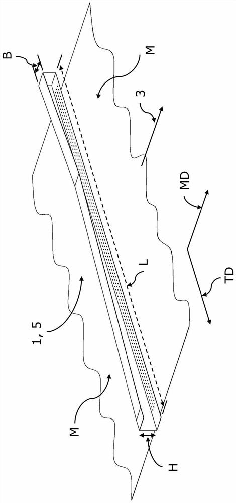
[0036] Discuss first figure 1 , which shows the blowing nozzle 1 according to the invention in a schematic three-dimensional representation.

[0037] Here, by figure 1 It can be seen that the mentioned blowing nozzle 1 is arranged, for example, above a moving material strip M which moves in the drawing-off direction in the direction of the arrow 3 . The material strip M is, for example, a plastic film stretched in a stretching device. The stretching device may be a transverse stretching device, a longitudinal stretching device or a sequential stretching device comprising, for example, longitudinal and transverse stretching stages or even a simultaneous stretching device.

[0038] exist figure 1 The blowing nozzles shown in are generally arranged not only on one side of the material strip M removed from below, but preferably symmetrically on both sides, that is to say above and below the material strip M at a distance of The mentioned is preferably arranged at a small distanc...


PUM


Abstract

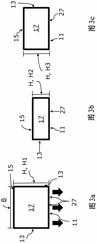
The invention relates to an improved blowing nozzle, in particular for stretching systems, which is characterised by the following features, inter alia: the nozzle box is divided in its longitudinal direction into at least two regions, specifically a first longitudinal region closer to the inflow side and a second longitudinal region that is subsequent and / or downstream and / or further away from the inflow side,the first longitudinal region is convergent or comprises at least one convergent portion in which the height between the lower face and the upper face is smaller than the height in the region of the inflow side as the distance from the inflow side increases, and the second longitudinal region is divergent or comprises at least one divergent portion in which the height between the lower face and the upper face is greater than the height at the end of the first longitudinal region and / or at the beginning of the second longitudinal region as the distance from the inflow side increases.

Description

technical field [0001] The invention relates to an air blow nozzle according to the preamble of claim 1 . Background technique [0002] Blowing nozzles are used, for example, to heat or cool strip-shaped materials, especially in the production of plastic films. Such ventilation nozzles are arranged above and / or below the material strip transversely, ie generally perpendicularly, to the withdrawal direction of the material strip and thus transversely to the transport direction of the strip. [0003] In order to heat or cool the film, for example, to production-specific temperatures for the stretching process within the transverse stretching device (TDO), nozzle boxes up to 15 m long with different outflow openings can be used. These nozzle boxes are usually supplied with the heat transfer medium used, for example air, on one side via pumps or blowers. Within the nozzle box volume, the air used is distributed, for example, over the working width of the nozzle and then flows ...

Claims


Application Information

Patent Timeline
Patent Type & Authority Applications(China)
IPC IPC(8): B29C35/16B29C55/02
CPCB29C35/16B29C55/02B29C2035/1658B29C55/28B29C35/045B29C35/002F04D29/403B05B1/205B05B1/24
Inventor C·赫格劳尔G·瓦尔德利特纳
Owner BRUECKNER MASCHB
Learn More