

Hub cover with radar and infrared stealth functions
A hubcap and infrared technology, applied in the direction of wheel cover discs, wheels, coatings, etc., can solve the problem of improving the stealth function, and achieve the effects of high absorption rate, good radar stealth performance, and low reflectivity
- Summary
- Abstract
- Description
- Claims
- Application Information
AI Technical Summary
Problems solved by technology
Method used
Image

Examples
Embodiment 1
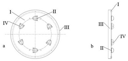
[0028] Such as figure 1 As shown, the hub cover with both radar and infrared stealth functions is composed of a disc plate I, a diversion groove II, an annular corner piece III, and a diversion ear IV. A diversion groove II is arranged on one side of the disc plate I, and a diversion ear IV is arranged above the diversion groove II; the other side of the disc plate I is covered with metal foil; the metal foil is sprayed with a thermal retroreflective coating. The annular corner piece III is connected with the disc plate I by riveting.
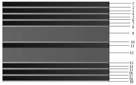
[0029] Such as figure 2 As shown, the disc plate consists of the first fiberglass layer 1, the first absorbing cloth layer 2, the second fiberglass layer 3, the second absorbing cloth layer 4, the third fiberglass layer 5, the third absorbing cloth layer 6, the fourth FRP layer 7, fourth absorbing cloth layer 8, first aramid honeycomb layer 9, fifth absorbing cloth layer 10, fifth FRP layer 11, second aramid honeycomb layer 12, sixth absorbi...
Embodiment 2
[0035] Such as figure 1 As shown, the hub cover with both radar and infrared stealth functions is composed of a disc plate I, a diversion groove II, an annular corner piece III, and a diversion ear IV. A diversion groove II is arranged on one side of the disc plate I, and a diversion ear IV is arranged above the diversion groove II; the other side of the disc plate I is covered with metal foil; the metal foil is sprayed with a thermal retroreflective coating. The annular corner piece III is connected with the disc plate I by riveting.
[0036] Such as figure 2 As shown, the disc plate consists of the first fiberglass layer 1, the first absorbing cloth layer 2, the second fiberglass layer 3, the second absorbing cloth layer 4, the third fiberglass layer 5, the third absorbing cloth layer 6, the fourth FRP layer 7, fourth absorbing cloth layer 8, first aramid honeycomb layer 9, fifth absorbing cloth layer 10, fifth FRP layer 11, second aramid honeycomb layer 12, sixth absorbi...
Embodiment 3
[0042] Such as figure 1 As shown, the hub cover with both radar and infrared stealth functions is composed of a disc plate I, a diversion groove II, an annular corner piece III, and a diversion ear IV. A diversion groove II is arranged on one side of the disc plate I, and a diversion ear IV is arranged above the diversion groove II; the other side of the disc plate I is covered with metal foil; the metal foil is sprayed with a thermal retroreflective coating. The annular corner piece III is connected with the disc plate I by riveting.
[0043] Such as figure 2 As shown, the disc plate consists of the first fiberglass layer 1, the first absorbing cloth layer 2, the second fiberglass layer 3, the second absorbing cloth layer 4, the third fiberglass layer 5, the third absorbing cloth layer 6, the fourth FRP layer 7, fourth absorbing cloth layer 8, first aramid honeycomb layer 9, fifth absorbing cloth layer 10, fifth FRP layer 11, second aramid honeycomb layer 12, sixth absorbi...
PUM
| Property | Measurement | Unit |
|---|---|---|
| thickness | aaaaa | aaaaa |
| thickness | aaaaa | aaaaa |
| thickness | aaaaa | aaaaa |
Abstract
Description
Claims
Application Information