A lifting device for the river

A lifting equipment and river channel technology, which is applied to cranes, mechanically driven excavators/dredgers, load hoisting elements, etc. The effect of pressure to improve cleaning efficiency

Active Publication Date: 2022-01-18
XINXIANG UNIV
View PDF12 Cites 0 Cited by
  • Summary
  • Abstract
  • Description
  • Claims
  • Application Information

AI Technical Summary

Problems solved by technology

Lifting equipment on land is difficult to adapt to the underwater environment and is easily damaged

Method used


Image

  • A lifting device for the river
  • A lifting device for the river
  • A lifting device for the river

Examples


Embodiment Construction

[0031] Lifting device structure

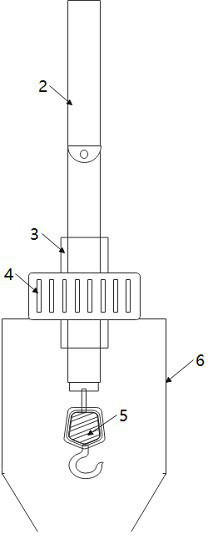
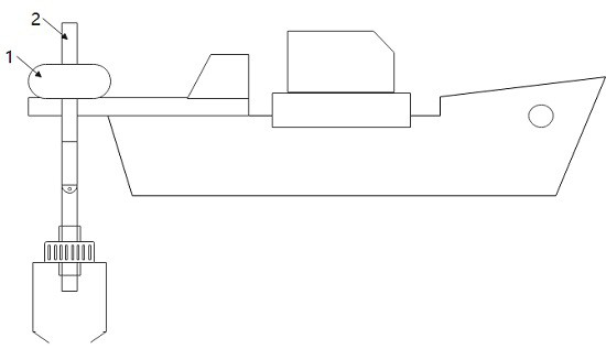
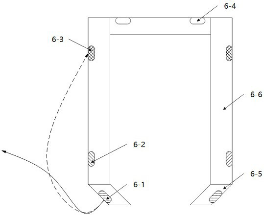
[0032] The lifting device includes a driver 1, a connecting rod 2, a lifting device 3, a rotating motor 4, a hook 5, and a dredging protection device 6.

[0033] Wherein the driver 1 is installed on ships, shores, bridges and other positions, and is used to provide driving force for lifting objects. The driver 1 is engaged with the connecting rod 2, driven by the driver 1, the connecting rod 2 can move up and down.

[0034] The connecting rod 2 includes a plurality of sub-connecting rods, which are connected to each other through a swing connecting device, so that the connecting rod 2 can swing in water in a limited manner with the water flow. One end of the connecting rod 2 is meshed with the driver 1 and is used to move up and down driven by the driver 1 to realize hoisting; the other end is connected to the lifting device 3 . The surface of the connecting rod 2 has teeth. Usually, the connecting rod 2 is a cuboid structure.

[0035] T...


PUM


Abstract

The invention relates to a hoisting device for a river course, comprising a driver, a connecting rod, a lifting device, a rotating motor, a hook and a dredging protection device. The connecting rod is a detachable limited swing connecting rod, and the dredging protection device realizes the cleaning of the river bottom sediment through the water suction nozzle. The device of the invention can be applied to the complex environment inside the river channel, making it possible to safely hoist the objects at the bottom of the river.

Description

technical field [0001] The invention relates to the field of cranes, in particular to the field of river lifting. Background technique [0002] Existing cranes are usually used for lifting on the ground at present, but there are some special occasions such as in the river, which are powerless for the lifting and hoisting of articles in the river. For example lifting the wreck of a shipwreck. This is because ordinary cranes usually use wire rope lifting, which is very convenient on land. However, due to the complex water flow environment in the river channel, the steel cable will swing irregularly with the water flow, especially when encountering turbulent flow. Not only is it difficult to align the underwater items to be hoisted like this, but also damage to the items will occur during hoisting and pulling up, and even decoupling, resulting in safety accidents. [0003] In addition, items at the bottom of the river are not arranged as regularly as on the ground. For exam...

Claims


Application Information

Patent Timeline
Patent Type & Authority Patents(China)
IPC IPC(8): B66C23/52B66C23/58B66C23/66B66C13/48E02F5/28E02F3/92
Inventor 张烨陈佼佼冉冉张烜贾蒙
Owner XINXIANG UNIV
Why Eureka
Try Eureka