Vehicle-mounted server equipment structure

A server and equipment technology, applied in the field of vehicle-mounted servers, can solve problems such as dust pollution on precision interfaces, block heat dissipation, and interface failures, and achieve high-efficiency ventilation and exhaust effects, rapid installation and disassembly, and position positioning.

Inactive Publication Date: 2021-11-30
潘圣凯
View PDF0 Cites 3 Cited by
  • Summary
  • Abstract
  • Description
  • Claims
  • Application Information

AI Technical Summary

Problems solved by technology

[0002] The vehicle-mounted server is also a high-performance computer that can reduce complexity and act as a network administrator. Currently, the vehicle-mounted server on the market has a single structure and is installed by direct connection. Good, but due to the particularity of driving, it will have a certain impact on the stable operation of the on-board server. Because the car will vibrate when it is in motion, and the long-term vibration will cause damage to the precision instruments in the server, so there is a sleeve outside the server. The protective shell, the server and the protective shell are protected by a shock-absorbing pad, but because the server generates a lot of heat when it is in use, the shock-absorbing pad will block the heat from dissipating, and if the heat is not dissipated, it will also cause damage to the server , but the current common fan ventilation and heat dissipation will cause low heat dissipation efficiency when the temperature is too high. Because the front end of the server is generally equipped with precision interfaces such as signal interfaces, transmitter interfaces, and network interfaces, and these precision interfaces are easy to use when not in use. Due to dust pollution, the interface will fail later, so it is necessary to protect the interface when not in use

Method used


Image

  • Vehicle-mounted server equipment structure
  • Vehicle-mounted server equipment structure
  • Vehicle-mounted server equipment structure

Examples


Embodiment Construction

[0025] The following will clearly and completely describe the technical solutions in the embodiments of the present invention with reference to the accompanying drawings in the embodiments of the present invention. Obviously, the described embodiments are only some, not all, embodiments of the present invention. Based on the embodiments of the present invention, all other embodiments obtained by persons of ordinary skill in the art without making creative efforts belong to the protection scope of the present invention.

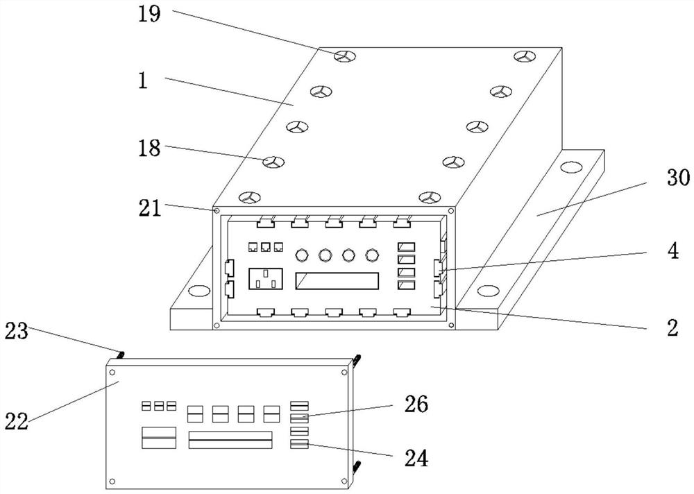
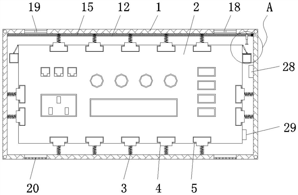
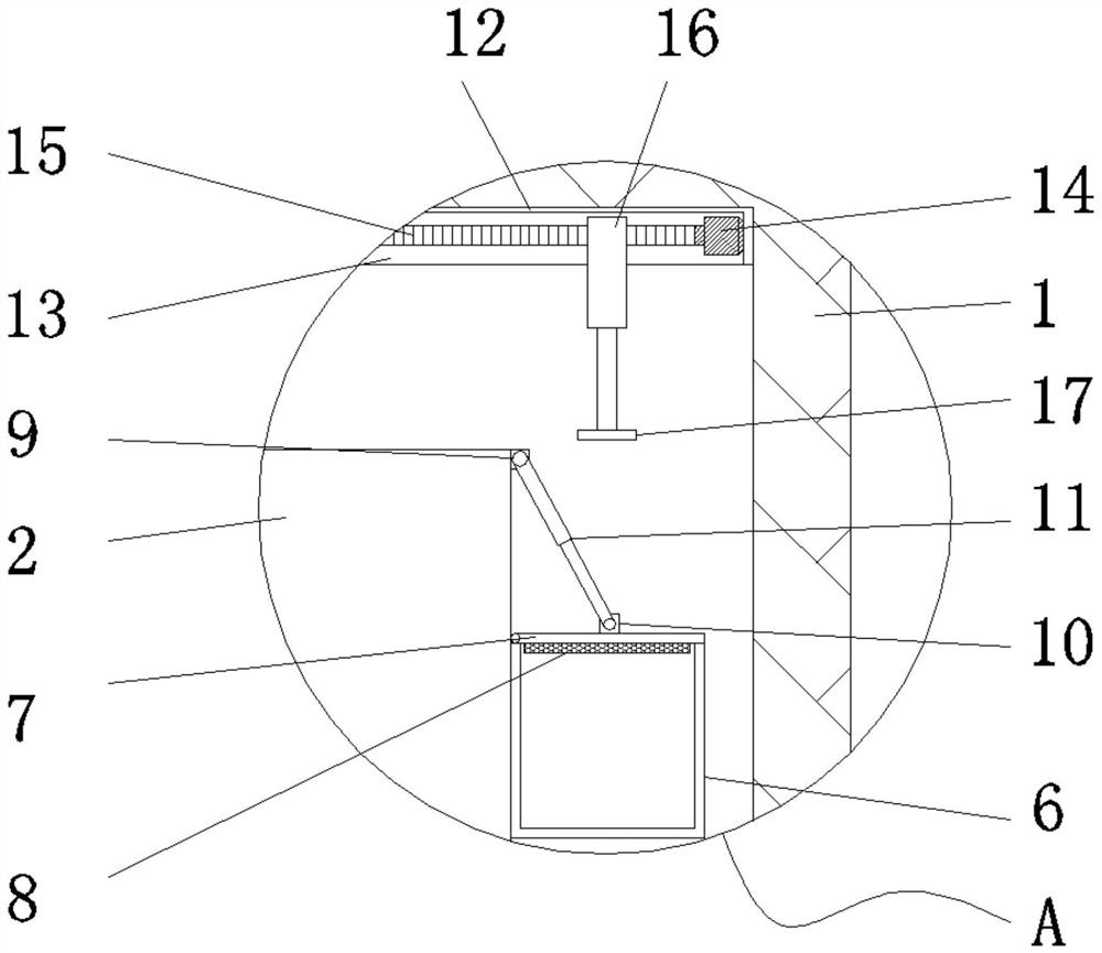
[0026] Such as Figure 1-5 As shown, the present invention provides a technical solution: a vehicle-mounted server device structure, including a protective case 1 and a main body 2. The protective case 1 is a hollow cuboid structure with an open front surface. The inner wall of the protective case 1 is fixedly connected with a plurality of The spring 3, the end of the spring 3 away from the protective shell 1 is fixedly connected with a slider 4, the outer wal...


PUM


Abstract

The invention relates to the technical field of vehicle-mounted servers, and discloses a vehicle-mounted server equipment structure. The vehicle-mounted server equipment structure comprises a protective shell and a main body, the protective shell is of a hollow cuboid structure with an opening in the front surface, a plurality of springs are fixedly connected to the inner side wall of the protective shell, and sliding blocks are fixedly connected to the ends, away from the protective shell, of the springs; a plurality of sliding grooves are formed in the outer side wall of the main body, the sliding blocks are located in the sliding grooves and are in sliding connection with the sliding grooves, a gap is reserved between the main body and the protective shell, the higher-efficiency ventilation and exhaust effect is achieved through a fan, a containing box is fixed to the outer side of the main body, and disinfection alcohol is contained in the containing box; and the sealing cover can be opened and closed through the first telescopic rod, the cleaning cotton and disinfection alcohol are soaked through the second telescopic rod, the motor drives the threaded rod to rotate so as to drive the second telescopic rod to move, the cleaning cotton makes contact with the main body, and rapid cooling treatment is achieved.

Description

technical field [0001] The invention relates to the technical field of vehicle-mounted servers, in particular to a structure of vehicle-mounted server equipment. Background technique [0002] The vehicle-mounted server is also a high-performance computer that can reduce complexity and act as a network administrator. Currently, the vehicle-mounted server on the market has a single structure and is installed by direct connection. Good, but due to the particularity of driving, it will have a certain impact on the stable operation of the on-board server. Because the car will vibrate when it is in motion, and the long-term vibration will cause damage to the precision instruments in the server, so there is a sleeve outside the server. The protective shell, the server and the protective shell are protected by a shock-absorbing pad, but because the server generates a lot of heat when it is in use, the shock-absorbing pad will block the heat from dissipating, and if the heat is not d...

Claims


Application Information

Patent Timeline
Patent Type & Authority Applications(China)
IPC IPC(8): G06F1/18G06F1/20H05K5/02
CPCG06F1/181G06F1/20H05K5/0217H05K5/03
Inventor 薛可宠潘圣凯张威潘智心赵清周增惠
Owner 潘圣凯
Why Eureka
Try Eureka