
Planetary directional high-speed braiding machine

A high-speed knitting machine and planetary technology, applied in the field of knitting machines, can solve the problems of increased vibration and noise of the machine, high friction of the slider structure, and inability to increase the speed, etc., to achieve reduced vibration and noise, small running resistance, and improved knitting effect Effect

Pending Publication Date: 2021-12-03
东莞市冠博精密机电有限公司
View PDF0 Cites 0 Cited by
  • Summary
  • Abstract
  • Description
  • Claims
  • Application Information

AI Technical Summary

Benefits of technology

This technology makes it possible for an improved spinning loom by allowing all its parts (spiners) on both the main frame and the shed can move together smoothly without any issues like getting stuck or causing damage during use. Additionally, this design reduces power usage compared with previous designs while still maintaining their benefits such as increased stability at high speeds and reduced wear caused by friction against other components within them.

Problems solved by technology

This patented technical problem addressed by this patents relates to improving the performance or efficiency of high-velocity woven fabrics during manufacturing processes that involve weaving threads onto fibers with an interchangeable guide rail system. These systems can generate too much wear on certain parts due to frequent changes between thread directions caused by the movement of the fiber ends themselves. To solve these issues, there have been developed various solutions involving reducing contact force between the fabric's yarns and rails while still allowing them smoothly move along their tracks.

Method used

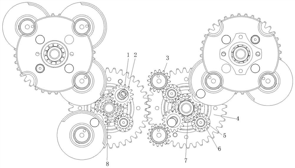
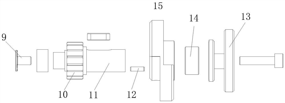
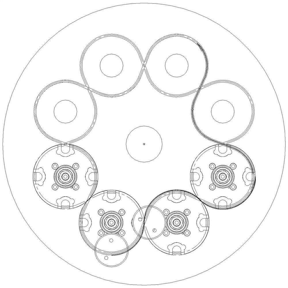

Image

  • Planetary directional high-speed braiding machine
  • Planetary directional high-speed braiding machine
  • Planetary directional high-speed braiding machine

Examples


Embodiment Construction

[0017] The following will clearly and completely describe the technical solutions in the embodiments of the present invention with reference to the accompanying drawings in the embodiments of the present invention. Obviously, the described embodiments are only some, not all, embodiments of the present invention. Based on the embodiments of the present invention, all other embodiments obtained by persons of ordinary skill in the art without making creative efforts belong to the protection scope of the present invention.

[0018] see Figure 1-3 , the present invention provides the following technical solutions: a planetary oriented high-speed knitting machine, comprising a rotor shaft external gear 8, the upper end of the rotor shaft external gear 8 is provided with a rotor shaft internal gear 7, and one side of the rotor shaft external gear 8 is provided with an outer planet Gear 2, an outer cam bearing 1 is arranged inside the outer planetary gear 2, an inner planetary gear 6...


PUM


Abstract

The invention discloses a planetary directional high-speed braiding machine, and belongs to the technical field of braiding machines. The planetary directional high-speed braiding machine comprises a rotor shaft outer gear; a rotor shaft inner gear is arranged at the upper end of the rotor shaft outer gear; an outer planetary gear is arranged on one side of the rotor shaft outer gear; an outer cam bearing is arranged in the outer planetary gear; an inner planetary gear is arranged on one side of the rotor shaft inner gear; and an inner cam bearing is arranged in the inner planetary gear. A planetary gear mechanism of a drive plate is adopted, so that a whole track of a spindle sliding block runs along a tangent track of the drive plate; a spindle thread outlet directs to the center of the machine while each spindle runs along the S-shaped track, so that the effect similar to a planet is achieved, the problem of angle swing and twisting of the thread outlet is solved, and the phenomena of abrasive damage, flanging and wire pressing of braided wires are avoided; and the planetary mechanism enables the braiding machine to be smaller in running resistance, lower in energy consumption, higher in rotating speed and higher in efficiency.

Description


Claims


Application Information

Patent Timeline
Owner 东莞市冠博精密机电有限公司
Learn More