Zero-calibration device and striker with the same, zero-calibration method, striking method
A striker and zero-calibration technology, applied in the field of zero-calibration devices, can solve problems such as inaccurate zero-calibration and achieve the effect of ensuring accuracy
- Summary
- Abstract
- Description
- Claims
- Application Information
AI Technical Summary
Problems solved by technology
Method used
Image
Examples
Embodiment 1
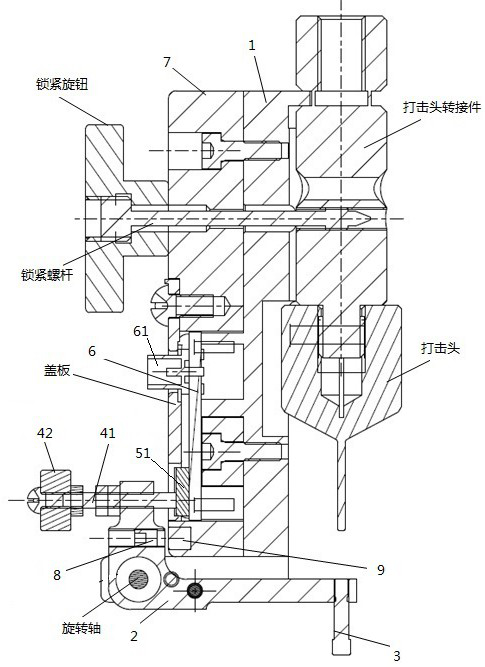
[0033] image 3 It is an exploded view of the zero calibration device provided in Embodiment 1 of the present invention provided on the striking head adapter. Figure 4 yes image 3 Sectional view along section line A1A2. Such as image 3 with Figure 4 As shown, the zero calibration device includes a bracket 1 , a lever 2 , a contact 3 , a first conductor 4 , a second conductor 5 and an insulating plate 7 . Bracket 1 supports other components of the zero calibration device. During zero calibration, the zero calibration device can also be locked to the striking head adapter through the bracket 1. The lever 2 is connected to the bracket 1 by a rotating shaft. Both bracket 1 and lever 2 are conductors. Place weights on both ends of lever 2. A first conductor 4 is arranged at the first end of the lever 2, and a contact 3 is arranged at the second end of the lever 2 to form a lever balance. Optionally, the distance from the first conductor 4 to the axis of rotation or the...
Embodiment 2
[0040] In the embodiment of the present invention, the basic structure of the zero calibration device is the same as that of the first embodiment, and the components that are the same as those of the first embodiment continue to use the same symbols as those in the first embodiment, including all the features described in the first embodiment. Let me repeat.
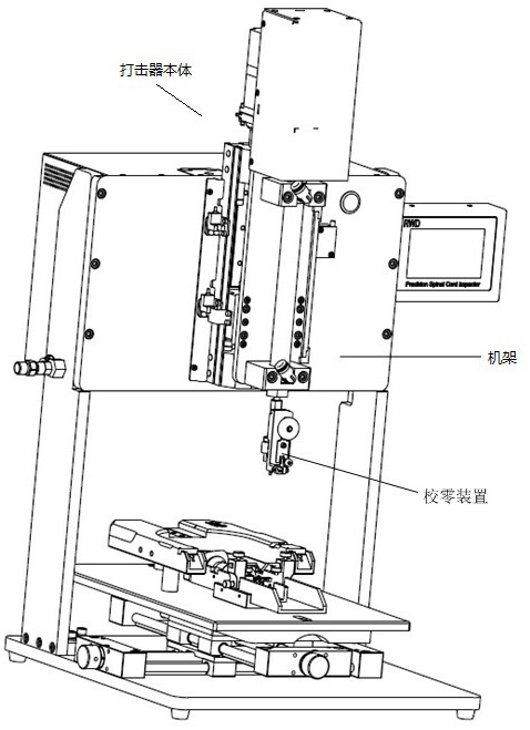
[0041] The percussion device provided by the embodiment of the present invention is as figure 1 , image 3 with Figure 4 As shown, the striker includes a power supply (not shown in the figure), striker body and zero calibration device. The striker body is connected to the power supply, and the zero calibration device is arranged on the striker body. The striker body includes a frame, a strike head and a strike head adapter. The striking head is connected to the rack through the striking head adapter. The striking heads include 1mm striking heads, 2mm striking heads, 3mm striking heads, 4mm striking heads, 5mm strik...
Embodiment 3
[0045] The zero calibration method provided by the embodiment of the present invention uses the percussion device described in the second embodiment to perform the zero calibration. The basic structure of the zero calibration device is the same as that of the first embodiment, and the components that are the same as those in the first embodiment continue to use the same symbols as those in the first embodiment. , including all the features described in Embodiment 1, which will not be repeated here. Such as Figure 8 As shown, the zero calibration method includes:
[0046] Step S801: The contact 3 moves along with the striking head.
[0047] Step S802: When the contact 3 reaches the striking position and receives force, the first conductor 4 and the second conductor 5 are disconnected.
[0048] Step S803: The striking head and the contactor 3 stop moving.
[0049] In the embodiment of the present invention, it is judged whether the striking position is reached by whether the...
PUM
 Abstract
Description
Claims
Application Information
 - R&D
- Intellectual Property
- Life Sciences
- Materials
- Tech Scout
- Unparalleled Data Quality
- Higher Quality Content
- 60% Fewer Hallucinations
Browse by: Latest US Patents, China's latest patents, Technical Efficacy Thesaurus, Application Domain, Technology Topic, Popular Technical Reports.
© 2025 PatSnap. All rights reserved.Legal|Privacy policy|Modern Slavery Act Transparency Statement|Sitemap|About US| Contact US: help@patsnap.com


