Plastic box automatic forming equipment
A technology of automatic molding and equipment, which is applied to household components, household appliances, and other household appliances, and can solve problems such as slow speed
- Summary
- Abstract
- Description
- Claims
- Application Information
AI Technical Summary
Problems solved by technology
Method used
Image

Examples
Embodiment 1
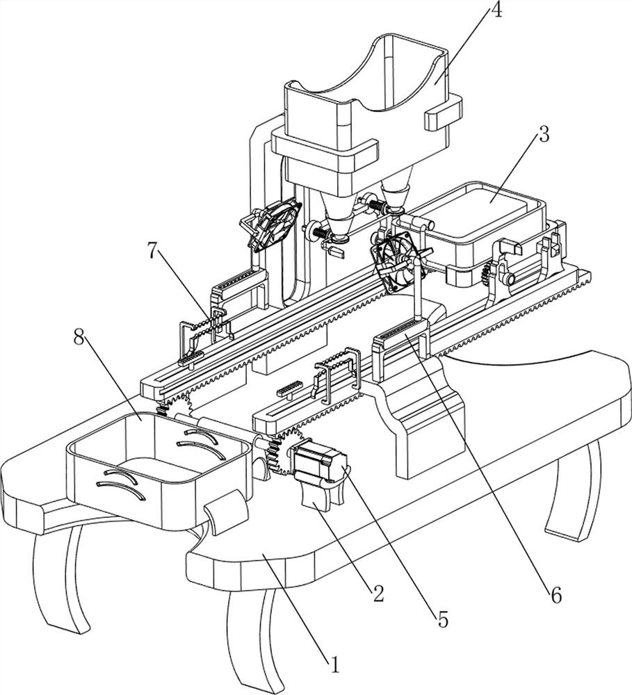
[0026] A plastic box automatic forming equipment, such as figure 1 As shown, it includes a base plate 1, a base 2, a manual pushing mechanism 3 and a material spraying mechanism 4. The base 2 is provided on the left front side of the upper part of the base plate 1, the manual pushing mechanism 3 is provided on the upper part of the base plate 1, and the right rear side of the upper part of the base plate 1 is provided. There are spraying mechanism 4.
[0027] When users need to make plastic boxes, they can use this device. First, place the raw materials for making plastic boxes in the spraying mechanism 4, and place the mold for making plastic boxes in the manual pushing mechanism 3. The material mechanism 3 moves the mold to just below the material injection mechanism 4 for blanking, so that the plastic box can be continuously made.
Embodiment 2
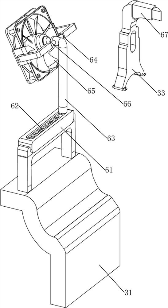
[0029] On the basis of Example 1, such as Figure 2-3 As shown, the manual pushing mechanism 3 includes a support plate 31, a first slide rail 32, a first slider 33, a first rotating rod 34, a supporting plate 35 and a mold frame 36, and the left side of the upper part of the base plate 1 is symmetrically arranged front and back. Support plate 31, the first slide rail 32 is all provided with on the support plate 31, and two first sliders 33 are all slidably arranged on the first slide rail 32, and the first rotation type is provided with the first rotation on the first slider 33. A supporting plate 35 is connected between the rod 34 and the first rotating rod 34 , and a mold frame 36 is placed on the upper part of the supporting plate 35 .
[0030] The user can push the first slider 33 and its upper part to move to the left along the first slide rail 32, so that when the mold frame 36 moves to the right below the spraying mechanism 4, the material is discharged to the mold fra...
Embodiment 3
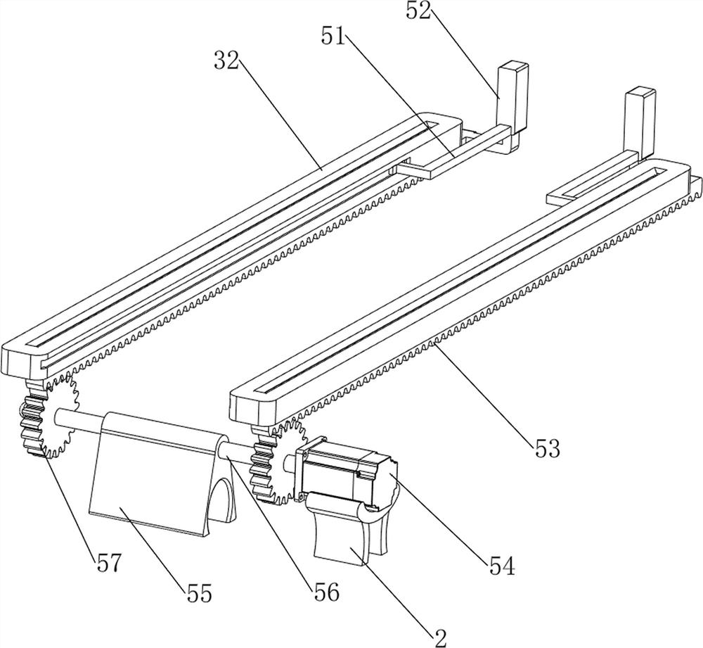
[0034] On the basis of Example 2, such as Figure 4-6 As shown, an automatic material pushing mechanism 5 is also included, and the automatic material pushing mechanism 5 includes a second slide block 51, a push plate 52, a first rack 53, a servo motor 54, a third support frame 55, a rotating shaft 56 and a first Gear 57, the first sliding rail 32 inner sliding type is provided with the second slider 51, the second slider 51 on both sides is connected with the supporting plate 35, the second slider 51 is provided with the first rack 53, the upper part of the base 2 Servomotor 54 is provided, and the left side of bottom plate 1 top is provided with the 3rd bracing frame 55, and the rotating type is provided with rotating shaft 56 on the 3rd bracing frame 55, and rotating shaft 56 is connected with the output shaft of servomotor 54, and both front and rear sides of rotating shaft 56 A first gear 57 is provided, and the first gear 57 meshes with the first rack 53 .
[0035]The u...
PUM
 Abstract
Description
Claims
Application Information
 - R&D Engineer
- R&D Manager
- IP Professional
- Industry Leading Data Capabilities
- Powerful AI technology
- Patent DNA Extraction
Browse by: Latest US Patents, China's latest patents, Technical Efficacy Thesaurus, Application Domain, Technology Topic.
© 2024 PatSnap. All rights reserved.Legal|Privacy policy|Modern Slavery Act Transparency Statement|Sitemap