
Illuminating textile article

a textile article and lamp technology, applied in the field of lamping textile articles, can solve the problems of difficult acceptance for consumers, approach cannot be excessively bent or stretched, and the printed circuit board used in the above-mentioned manner cannot be excessively bent or stretched, and achieve the effects of excellent flexibility, rapid manufacturing, and light weigh

Inactive Publication Date: 2012-10-09
HSU FU BIAU
View PDF6 Cites 74 Cited by
  • Summary
  • Abstract
  • Description
  • Claims
  • Application Information

AI Technical Summary

Benefits of technology

The solution achieves excellent flexibility, reduced weight, improved comfort, rapid and cost-effective manufacturing, and easy control over lighting, enabling larger area coverage and aesthetically pleasing designs while minimizing environmental impact.

Problems solved by technology

Obviously, the flexible printed circuit board utilized in the aforesaid approach can not be excessively bent or stretched due to its limited flexibility.
Nevertheless, the textile articles of the aforesaid approach can not get aesthetically pleasing design and wearing comfort like general textile articles, and therefore, they are difficult for consumers to accept.
Besides, if using flexible printed circuit boards with larger area, the aforesaid approach would result in that weight and thickness of finished textile articles are increased and the flexible printed circuit boards with fixed light-emitting diodes are more difficult to be integrated with general textile articles into aesthetically pleasing designs.
Furthermore, if changing layout of light-emitting diodes, the aforesaid approach must consume much time and cost to design the flexible printed circuit board renewedly.
Furthermore, the manufacture of flexible printed circuit board used in the aforesaid approach is heavy pollution process and harm to environment.
Due to poor wearing comfort and softness of those optical fibers or flexible light-conducting tubes and difficulty of connecting light sources with textile articles, the prior art has much limitation in practice and process.
Besides, the prior art can not approach requirements of textile articles with larger area and individual control over lighting points, and has lower illumination.

Method used


Image

  • Illuminating textile article
  • Illuminating textile article
  • Illuminating textile article

Examples


Embodiment Construction

[0027]Some preferred embodiments and practical applications of this present invention would be explained in the following paragraph, describing the characteristics, spirit and advantages of the invention.

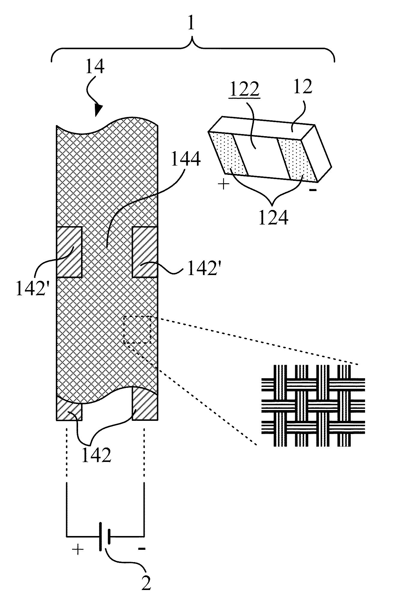
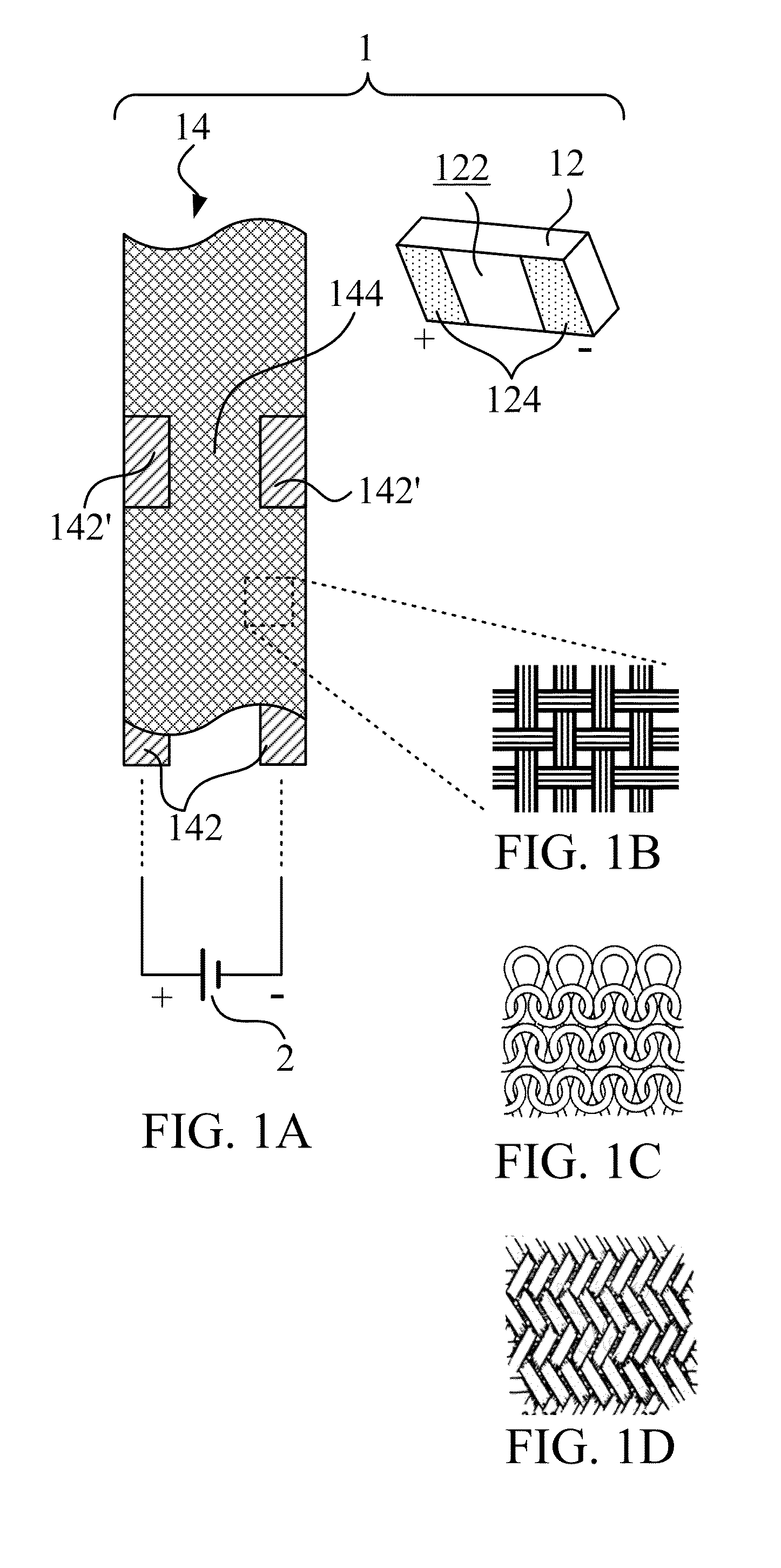
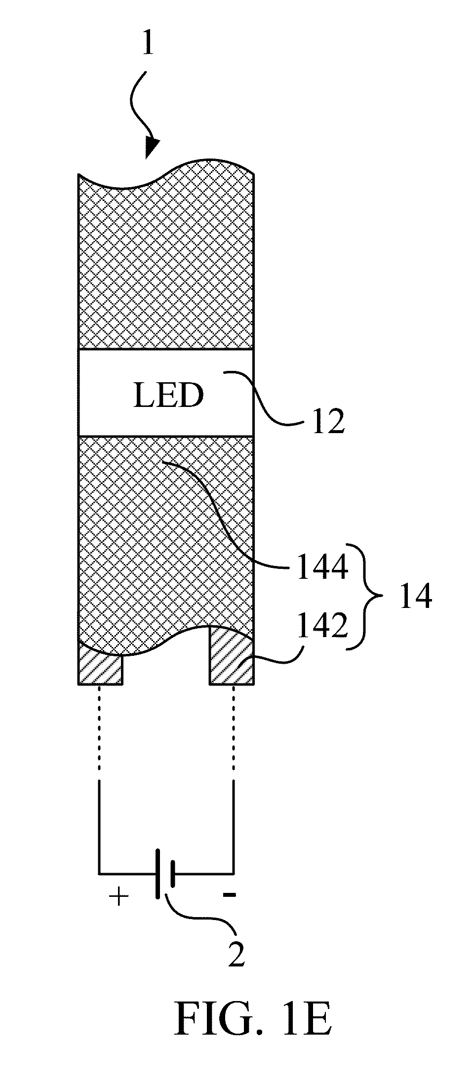
[0028]Referring to FIGS. 1A to 1E, those figures disclose an illuminating textile article 1 according to a preferred embodiment of the invention and possible main textile structures thereof.

[0029]As shown in FIG. 1A, the illuminating textile article 1 according to the preferred embodiment of the invention includes a diode-based lighting device 12 and a textile body 14. The diode-based lighting device 12 has M contact points 124 where M is an integer equal to or larger than 2. For explanation purpose only, FIG. 1A shows the diode-based lighting device 12 having two contact points 124 formed on a lower surface 122 thereof. In practical application, the diode-based lighting device 12 is, preferable but not limited to, a surface-mounted type of diode-based lighting device.

[0030]Also sho...


PUM

PropertyMeasurementUnit
sizeaaaaaaaaaa
sizeaaaaaaaaaa
conductiveaaaaaaaaaa

Abstract

The invention discloses an illuminating textile article including a diode-based lighting device and a textile body. The diode-based lighting device has M contact points where M is an integer equal to or larger than 2. The textile body is constituted by N conductive yarns and at least one non-conductive yarn where N is an integer equal to or larger than 2, and provides M′ conductive exposed portions of the conductive yarns which are separated by the at least one non-conductive yarn from one another. Each of the M contact points corresponds to one of the M′ conductive exposed portions and is fixed to the corresponding conductive exposed portion. The conductive yarns provide terminals for electric connection of a power supply.

Description

BACKGROUND OF THE INVENTION[0001]1. Field of the Invention[0002]This present invention relates to an illuminating textile article. Moreover, in particular, the illuminating textile article according to the invention is a textile article incorporating with LEDs (light-emitting diode), can be served as a product as requirement, and can be served as a textile yarn for another textile article.[0003]2. Description of the Prior Art[0004]Nowadays, light-emitting diodes have been used for a wide variety of applications, e.g., indication, display, illumination, etc. Combination of apparatuses and light-emitting diodes has been formerly practiced on electronic equipments with indicators, traffic lights, lighting fixtures, street lamps, and gradually emerged in textile such as clothing.[0005]One of current approaches regarding textile articles incorporating with light-emitting diodes is first to bond light-emitting diodes on a flexible printed circuit board, and then to attach the flexible pri...

Claims


Application Information

Patent Timeline
Patent Type & Authority Patents(United States)
IPC IPC(8): D03D15/00
CPCD03D1/0088D03D15/00D04B1/16D03D3/005Y10T428/2481D10B2101/06D10B2101/12D10B2101/20D10B2321/021D10B2321/022D10B2321/042D10B2321/10D10B2331/02D10B2331/04D10B2331/061D10B2401/16D10B2501/00F21K9/00Y10T428/249921Y10T442/339Y10T442/3976Y10T442/40Y10T442/30
Inventor HSU, FU-BIAUKUO, CHUN-JUNG
Owner HSU FU BIAU
Learn More