Multi-beam laser scanning system and method

a laser scanning and beam laser technology, applied in the direction of additive manufacturing processes, instruments, manufacturing tools, etc., can solve problems such as limited efficiency

Inactive Publication Date: 2014-07-17
GENERAL ELECTRIC CO
View PDF2 Cites 60 Cited by
  • Summary
  • Abstract
  • Description
  • Claims
  • Application Information

AI Technical Summary

Benefits of technology

[0004]In one embodiment, a multi-beam laser scanning system is provided. The system comprises a laser configured to generate an initial laser beam, and a beam splitter configured to split the initial laser beam into a first laser beam and a second laser beam. The system further comprises a first scanning unit configured to deflect the first laser beam along a desired direction, and a second scanning unit configured to deflect the second laser beam along a desired direction. A control unit is coupled to the first and second scanning units and arranged to output control signals to the first and second scanning units to manufacture an object.
[0005]In another embodiment, a multi-beam laser scanning system is provided. The system comprises a laser for generating an initial laser beam, a first beam splitter configured to split the initial laser beam into a first laser beam and a second laser beam, a second beam splitter configured to split the first laser beam into a third laser beam and a fourth laser beam, and a

Problems solved by technology

Laser rapid manufacturing technology uses one laser b

Method used


Image

  • Multi-beam laser scanning system and method
  • Multi-beam laser scanning system and method
  • Multi-beam laser scanning system and method

Examples


Embodiment Construction

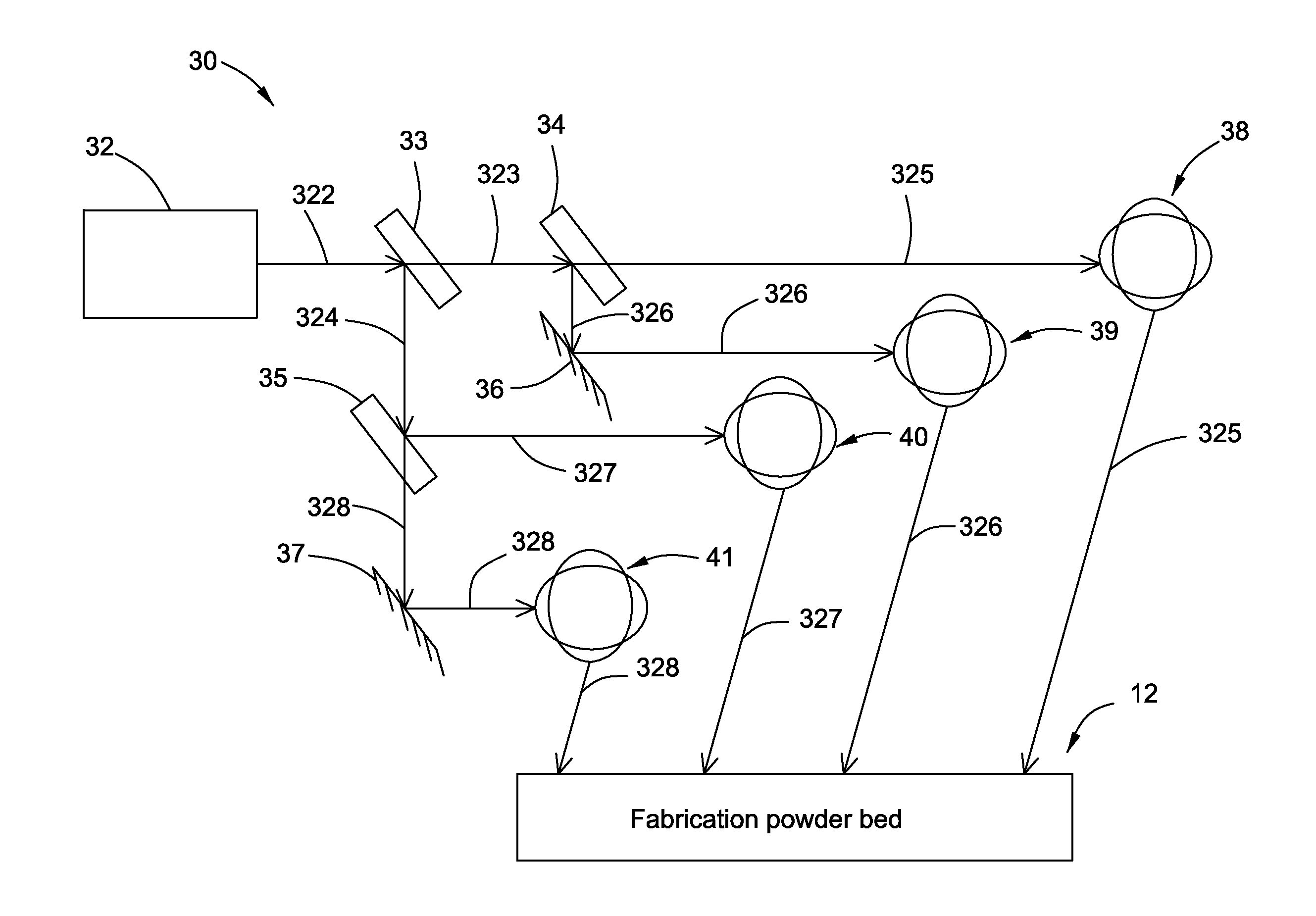
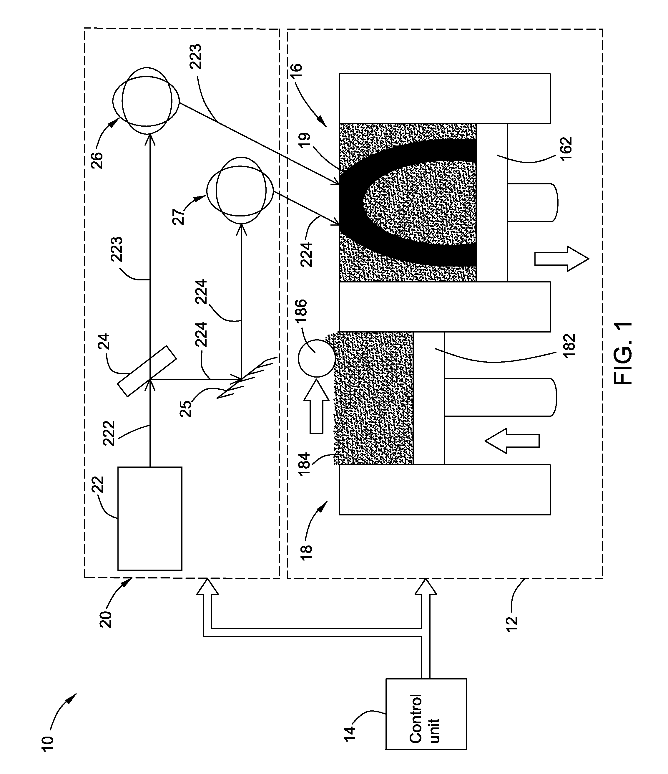
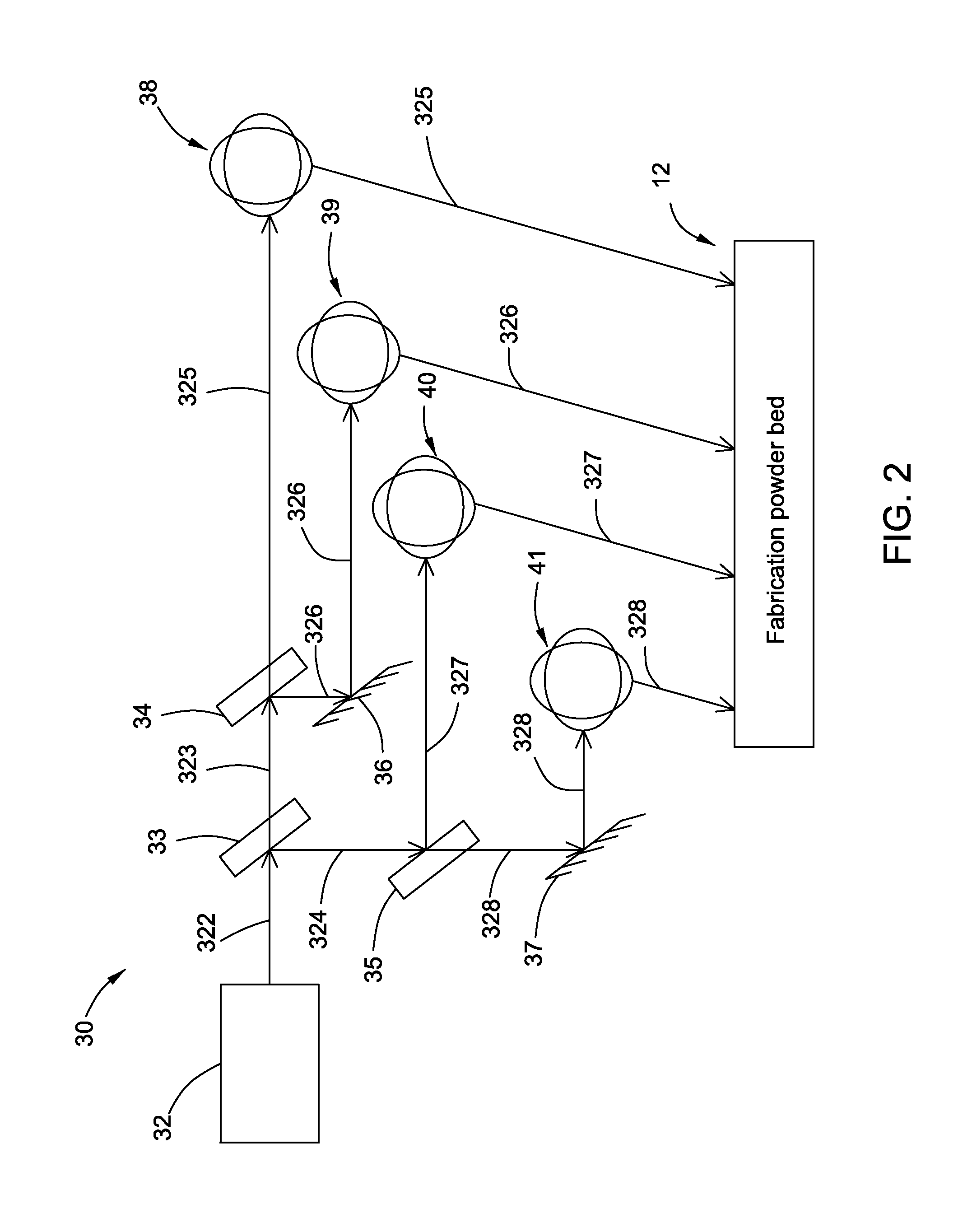
[0014]Embodiments of the invention relate to a multi-beam laser scanning system for performing rapid manufacturing of objects, such as 3D objects. The multi-beam laser scanning system comprises a laser, a beam splitter, a first scanning unit, a second scanning unit, and a control unit. The laser is used for generating an initial laser beam. The beam splitter is used for splitting the initial laser beam into a first laser beam and a second laser beam. The first scanning unit is used for deflecting the first laser beam along a desired direction. The second scanning unit is used for deflecting the second laser beam along a desired direction. The control unit is coupled to the first and second scanning units and arranged to output control signals to the first and second scanning units to manufacture an object.

[0015]Unless defined otherwise, technical and scientific terms used herein have the same meaning as is commonly understood by one of ordinary skill. The terms “first”, “second”, an...


PUM

PropertyMeasurementUnit
Poweraaaaaaaaaa

Abstract

A multi-beam laser scanning system comprising a laser, a beam splitter, a first scanning unit, a second scanning unit, and a control unit is disclosed herein. The laser is used for generating an initial laser beam. The beam splitter is used for splitting the initial laser beam into a first laser beam and a second laser beam. The first scanning unit is used for deflecting the first laser beam along a desired direction. The second scanning unit is used for deflecting the second laser beam along a desired direction. The control unit is coupled to the first and second scanning units and arranged to output control signals to the first and second scanning units to manufacture an object.

Description

BACKGROUND OF THE INVENTION[0001]Objects such as three-dimensional (3D) objects such as collimators used in x-ray imaging devices can be manufactured using laser rapid manufacturing (or free form fabrication) technology. One laser rapid manufacturing approach uses a laser beam to scan across and selectively polymerize a monomer (i.e., solidify a liquid plastic) to build up a prototype layer-by-layer and line-by-line from a predetermined model of a 3D object. The laser beam is focused on a portion of a bath of liquid resin which causes the liquid to polymerize (or solidify) where the focal point of the laser beam contacts (i.e., is incident on) the liquid. This technique allows a 3D object to be rapidly produced that would otherwise take a long time to make through a molding process.[0002]Laser beams are used to perform selective laser sintering / melting of a powder in laser rapid manufacturing technology. Laser sintering / melting is a process in which the temperature of a powdered mat...

Claims


Application Information

Patent Timeline
IPC IPC(8): G02B26/12
CPCG02B26/123B29C64/153B33Y30/00B29C64/268
Inventor LI, YANMINGUO, RUITANIKHLEF, ABDELAZIZCHEN, XIAOBINCAI, GUOSHUANGPENG, ZHIXUEXU, WENLONGLI, PENG
Owner GENERAL ELECTRIC CO
Why Eureka
Try Eureka