
Injection molding process for center shaft of conductive slip ring

A conductive slip ring and process technology, which is applied in the field of injection molding of conductive slip ring central shafts, can solve problems such as inconvenient sealing processing, copper ring position deviation, and flat copper ring injection shaking, etc., to ensure placement stability and avoid problems. The effect of deviation, ensuring accuracy

Pending Publication Date: 2021-12-07
徐洪杰
View PDF7 Cites 0 Cited by
  • Summary
  • Abstract
  • Description
  • Claims
  • Application Information

AI Technical Summary

Problems solved by technology

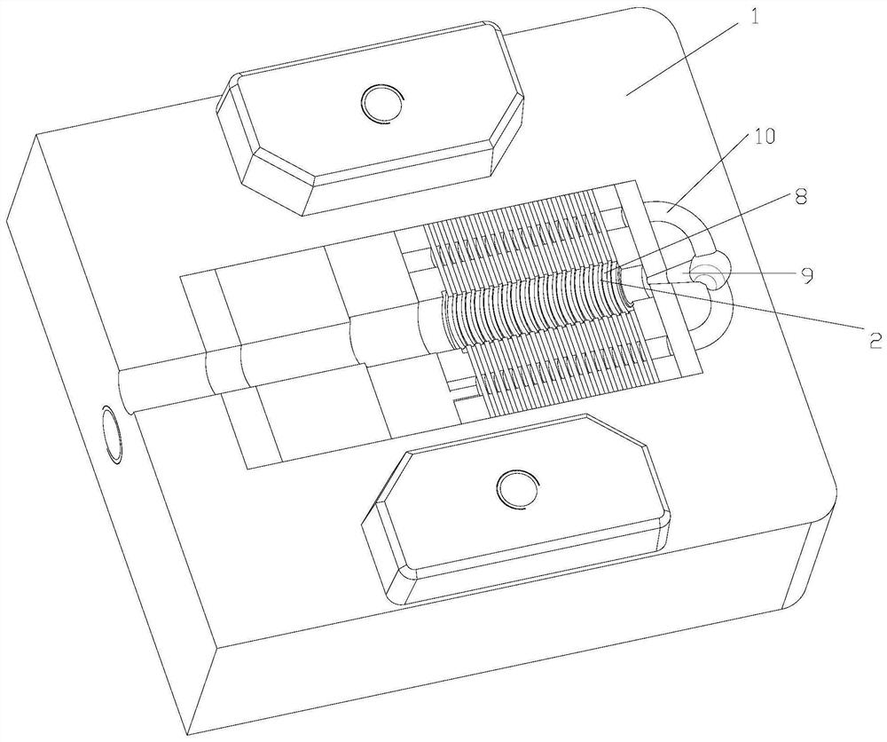
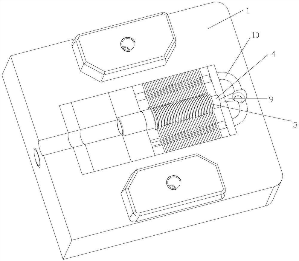
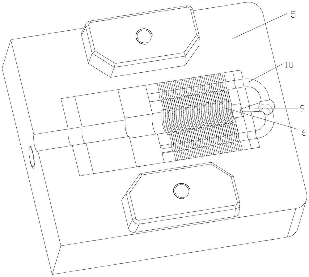
[0003] In the process of manufacturing the central shaft of the conductive slip ring, it is necessary to install multiple copper rings on the periphery, and at the same time, the multiple copper rings need to be separated by spacer rings. The existing technology is processing spacer rings and copper rings. Usually, the copper ring is placed in the mold first, and then the spacer ring and the shaft body are directly formed by injection molding. However, in this molding process, both sides of the copper ring will be squeezed by the injection molding material, making The position of the copper ring is offset, which is not conducive to the forming accuracy of the middle shaft of the conductive slip ring
[0004] At the same time, when the copper ring is injected, it is necessary to seal the radial position on both sides of the copper ring first, but when the flat copper ring is injected, the two sides of the flat copper ring are not convenient for sealing, so it is impossible The flat copper ring is fixed and limited by sealing glue, so the flat copper ring may shake during injection molding

Method used


Image

  • Injection molding process for center shaft of conductive slip ring
  • Injection molding process for center shaft of conductive slip ring
  • Injection molding process for center shaft of conductive slip ring

Examples


Embodiment Construction

[0036] The following will clearly and completely describe the technical solutions in the embodiments of the present invention with reference to the accompanying drawings in the embodiments of the present invention. Obviously, the described embodiments are only some, not all, embodiments of the present invention. All other embodiments obtained by persons of ordinary skill in the art based on the embodiments of the present invention belong to the protection scope of the present invention.

[0037] Those skilled in the art should understand that in the disclosure of the present invention, the terms "vertical", "transverse", "upper", "lower", "front", "rear", "left", "right", " The orientation or positional relationship indicated by "vertical", "horizontal", "top", "bottom", "inner", "outer", etc. is based on the orientation or positional relationship shown in the drawings, which are only for the convenience of describing the present invention and The above terms should not be con...


PUM


Abstract

The invention provides an injection molding process for a center shaft of a conductive slip ring. The method comprises the following steps that copper rings are sequentially placed on a plurality of first copper ring mounting positions, the first copper ring mounting positions are positioned on a first machining position in a first lower mold, and the plurality of copper rings are arranged at intervals; a first upper mold covers the first lower mold, and an injection molding material is injected into an injection molding space formed on the inner sides of the copper rings; after the injection molding material is cured, a shaft body penetrating through the multiple copper rings is formed, and a one-time formed workpiece is obtained; the one-time formed workpiece is placed on a second machining position on a second lower mold, and a plurality of first spacer ring injection molding positions are arranged on the second machining position; a second upper mold covers the second lower mold, and an injection molding material is injected into the first spacer ring injection molding positions; and after the injection molding material is cured, a spacer ring is formed in the first spacer ring injection molding positions, and a secondarily-formed workpiece is obtained. When the flat copper rings are subjected to injection molding, the injection molding procedure is completed through the axial first positioning technology under the condition that no sealing glue exists in the radial direction.

Description

technical field [0001] The invention relates to the field of manufacture of a central shaft of a conductive slip ring, in particular to an injection molding process of a central shaft of a conductive slip ring. Background technique [0002] Conductive slip rings are also called conductive rings, slip rings, collector rings, collector rings, etc. It can be used in any electromechanical system that requires continuous rotation while simultaneously transmitting power and signals from a fixed position to a rotating position. Slip rings can improve system performance, simplify system structure, and prevent wires from being twisted during rotation; the central shaft of conductive slip rings is an important part of conductive slip rings. [0003] In the process of manufacturing the central shaft of the conductive slip ring, it is necessary to install multiple copper rings on the periphery, and at the same time, the multiple copper rings need to be separated by spacer rings. The ex...

Claims


Application Information

Patent Timeline
IPC IPC(8): B29C45/14B29C45/26B29C45/27B29L31/34
CPCB29C45/14B29C45/14065B29C45/26B29C45/27B29L2031/34Y02E10/72
Inventor 徐洪杰
Owner 徐洪杰
Learn More