Pressure maintaining jig

A technology for jigs and pressing parts, applied in the direction of presses, manufacturing tools, etc., can solve the problems of increased pressure maintaining cost, inability to achieve pressure maintaining effect, and increase the structural design complexity of pressure maintaining fixtures, so as to reduce the volume , the effect of reducing the structural complexity

Pending Publication Date: 2021-12-07
GUANGDONG OPPO MOBILE TELECOMM CORP LTD
View PDF0 Cites 0 Cited by
  • Summary
  • Abstract
  • Description
  • Claims
  • Application Information

AI Technical Summary

Problems solved by technology

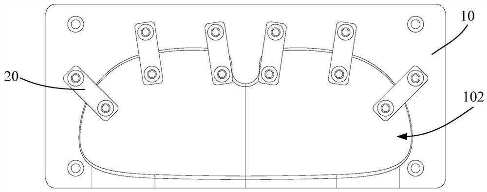
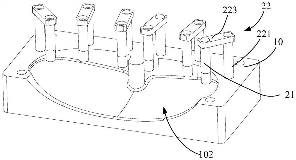
Therefore, for products with a large curved surface or other irregular shapes like smart glasses, if the above-mentioned pressure-holding fixture is used for pressure-holding, it will not be able to achieve an effective pressure-holding effect. Improving the shape of the pressure holding jig not only increases the complexity of the internal structure design of the pressure holding jig, but also requires a larger volume of the pressure holding jig to cover the front mask, as well as the pressure inside the pressure holding jig. Set the buckle, so that the cost of holding pressure will increase significantly

Method used


Image

  • Pressure maintaining jig
  • Pressure maintaining jig
  • Pressure maintaining jig

Examples


Embodiment Construction

[0017] Example embodiments will now be described more fully with reference to the accompanying drawings. Example embodiments may, however, be embodied in many forms and should not be construed as limited to the examples set forth herein; rather, these embodiments are provided so that this disclosure will be thorough and complete and will fully convey the concept of example embodiments to those skilled in the art. The drawings are merely schematic illustrations of the present disclosure and are not necessarily drawn to scale. The same reference numerals in the drawings denote the same or similar parts, and thus repeated descriptions thereof will be omitted.

[0018] Furthermore, the described features, structures, or characteristics may be combined in any suitable manner in one or more embodiments. In the following description, numerous specific details are provided in order to give a thorough understanding of embodiments of the present disclosure. However, those skilled in ...


PUM


Abstract

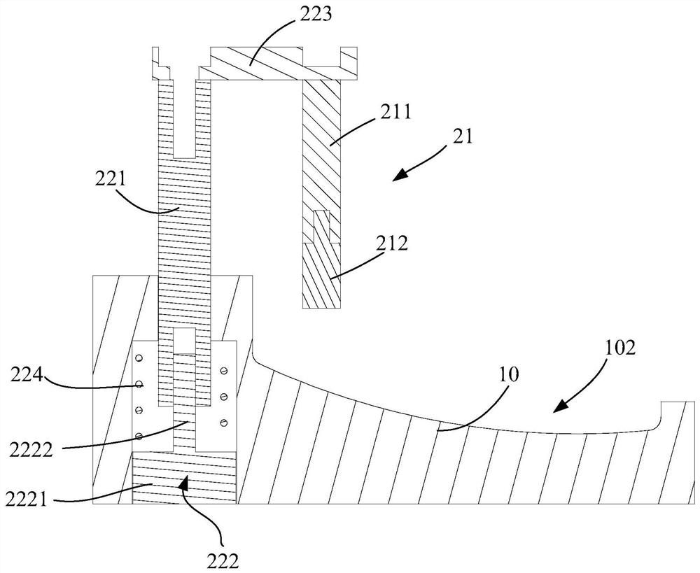
The invention provides a pressure maintaining jig. The pressure maintaining jig comprises a base and pressure maintaining mechanisms. The base is used for supporting a piece to be subjected to pressure maintaining; the pressure maintaining mechanisms comprise pressing pieces and driving assemblies in driving connection with the pressing pieces, the driving assemblies are installed on the base, and the driving assemblies are used for driving the pressing pieces to move so as to be pressed on the surface of the piece to be subjected to pressure maintaining; and the multiple pressure maintaining mechanisms are arranged, and the multiple pressure maintaining mechanisms are arranged in a dispersed manner so that the pressing pieces of the multiple pressure maintaining mechanisms can jointly carry out pressure maintaining on the piece to be subjected to pressure maintaining. By means of the pressure maintaining jig, pressure maintaining can be carried out on special-shaped products.

Description

technical field [0001] The present disclosure relates to the field of electronic equipment, in particular to a pressure holding fixture. Background technique [0002] At present, during or after assembly of electronic equipment, it is usually necessary to use a pressure-holding jig to maintain pressure, so as to improve the connection fastness of the bonding structure or the clamping structure in the electronic equipment. In the related art, the pressure maintaining fixture is generally divided into an upper cover and a lower cover, and the upper cover and the lower cover clamp the electronic equipment, thereby realizing the pressure maintaining of the electronic equipment. [0003] However, this type of pressure-holding jig can only be used for pressure-holding electronic devices with relatively flat surfaces, such as mobile phones. For smart glasses, the surface of the front mask presents a curved surface with a certain degree of curvature. From the perspective of the thi...

Claims


Application Information

Patent Timeline
IPC IPC(8): B30B9/28
CPCB30B9/28
Inventor 王锐添朱昕予
Owner GUANGDONG OPPO MOBILE TELECOMM CORP LTD
Why Eureka
Try Eureka