

A movable emergency bridge device for road bridges
A technology for bridges and emergency bridges, applied to bridges, bridge parts, bridge forms, etc., can solve problems such as insufficient strength, emergency bridges affecting the passage of emergency personnel, and hidden safety hazards, and achieve the effect of improving load capacity
- Summary
- Abstract
- Description
- Claims
- Application Information
AI Technical Summary
Problems solved by technology
Method used
Image


Examples
Embodiment 1
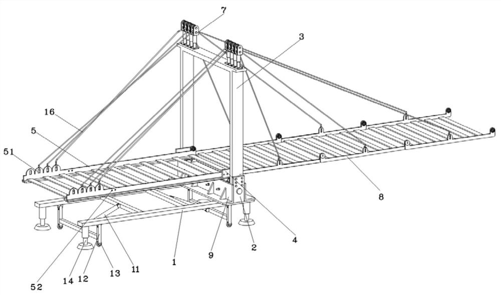
[0028] like Figure 1 to Figure 9 As shown, the present invention provides a movable emergency bridge device for road bridges, comprising a bottom support frame 1, a fixing member 2 is arranged at the right end of the bottom support frame 1, a beam 3 is installed on the fixing member 2, and the bottom of the inner side of the beam 3 is provided with a fixing member 2. A limit card 4 and a pulley block 6 are slidably connected to the top of the pulley block 6 with a sliding frame 5 , a plurality of extension frames 8 are connected in series on the right end of the sliding frame 5 , and a cable frame 7 is fixedly installed on the top of the beam 3 .
[0029] The limit clip 4 is hinged with the inner side of the beam 3, and the limit clip 4 is provided with a hole through which the bolt passes, and the inner side of the beam 3 is fixed with a nut matched with the bolt. By passing the bolt through the hole on the limit clip 4 and The fixing of the limit card plate 4 can be complet...
Embodiment 2
[0044] As a further improvement of the above technical solution, when an emergency situation occurs and the emergency bridge needs to be quickly retracted, the emergency bridge can be retracted quickly in the following manner.
[0045] When the emergency bridge needs to be retracted quickly, first control the retraction of the second electromagnetic latch 84 on the first extension frame 8 on the side of the sliding frame 5 to unlock the sliding frame 5 and the first extension frame 8, and then control the first extension frame 8 by controlling the first extension frame 8. The first electric telescopic rod 72 under the sling 16 corresponding to one extension frame 8 is extended. Since the sliding frame 5 is unlocked from the first extension frame 8, the first extension frame 8 can rotate relative to the sliding frame 5, and the first extension frame 8 can rotate relative to the sliding frame 5. The electric telescopic rod 72 is extended, so that the first extension frame 8 is ro...
Embodiment 3
[0048] As a further improvement of the above technical solution, when the flood rises, because the emergency bridge is submerged by the flood, rescuers and trapped persons cannot directly observe the position of the emergency bridge with the naked eye, but can only touch and test the position of the emergency bridge by footsteps. The passing speed of the rescuers and the trapped persons is to ensure that even if the emergency bridge encounters a rising flood, the passing speed of the rescuers and the trapped persons is not affected, and the rescue is carried out according to the method described in this embodiment.
[0049] When the flood rises, the second electromagnetic latch 84 on the first extension frame 8 can be controlled to shrink, and at the same time, the first electric telescopic rod 72 under the sling 16 corresponding to the first extension frame 8 can be controlled to extend, Rotate the first extension frame 8 upwards, when it rotates up to a suitable height, stop ...
PUM
 Abstract
Description
Claims
Application Information