Photovoltaic tile assembly and photovoltaic roof

A photovoltaic module and photovoltaic tile technology, applied in photovoltaic modules, photovoltaic power generation, roof insulation materials, etc., can solve the problem that the left and right frames and the lower frame cannot be effectively protected against lightning.

Pending Publication Date: 2021-12-07
东方日升(宁波)新能源有限公司
View PDF0 Cites 0 Cited by
  • Summary
  • Abstract
  • Description
  • Claims
  • Application Information

AI Technical Summary

Problems solved by technology

[0003] In some existing BIPV systems, it is usually necessary to use the left and right frames and the bottom frame for lap installation, and it is necessary to form a stable connection structure between the left and right frames and the bottom frame to fix the photovoltaic modules. In order to improve the anticorrosion of the left and right frames and the bottom frame In the prior art, the surface of the frame usually has a protective layer with good insulation, which leads to the ineffective lightning protection of the left and right frames and the bottom frame.

Method used


Image

  • Photovoltaic tile assembly and photovoltaic roof
  • Photovoltaic tile assembly and photovoltaic roof
  • Photovoltaic tile assembly and photovoltaic roof

Examples


Embodiment 1

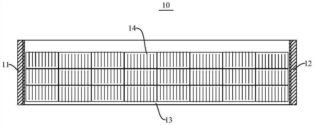
[0052] This embodiment provides a photovoltaic tile assembly 10, please refer to figure 1 , which includes a frame, connectors and photovoltaic modules 14 . Wherein, the frame includes a first frame 11 , a second frame 12 and a third frame 13 .

[0053] The photovoltaic assembly 14 includes opposite first and second ends and opposite third and fourth ends, wherein the first and second ends of the photovoltaic assembly 14 are respectively fixed to the first frame 11 and the second frame 12, The third end of the photovoltaic module 14 is fixed on the third frame 13 . When two photovoltaic tile assemblies 10 are connected, the first frame 11 of one photovoltaic tile assembly 10 forms a detachable connection structure with the second frame 12 of the other photovoltaic tile assembly 10 .

[0054] Exemplarily, the photovoltaic module 14 includes a photovoltaic battery sheet, an upper cover plate, a back plate, and an encapsulation film. The specific order of the structure of the ...

Embodiment 2

[0088] This embodiment provides a photovoltaic roof 100 (refer to Figure 8 ), which is assembled from a plurality of photovoltaic tile assemblies 10 of Embodiment 1.

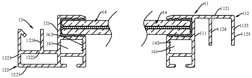
[0089] Among the two adjacently arranged photovoltaic tile assemblies 10, the first abutting member 112 of one photovoltaic tile assembly 10 is against the second abutting surface 121 of the adjacent photovoltaic tile assembly 10, and the adjacently arranged photovoltaic tile assemblies The second abutting part 122 of the assembly 10 is abutted against the first abutting surface 111 of the photovoltaic tile assembly 10 .

[0090] When assembling, the first abutment part 112 of the photovoltaic tile assembly 10 is pressed against the second abutment surface 121 of the adjacent photovoltaic tile assembly 10, and the second abutment part 122 of the adjacent photovoltaic assembly 14 is abutted against The photovoltaic roof 100 of this embodiment is formed by holding on the first abutting surface 111 of the photovo...

Embodiment 3

[0094] This embodiment provides a photovoltaic tile assembly 10 . Compared with the photovoltaic tile assembly 10 of Embodiment 1, the difference lies in that the first abutting member 112 of this embodiment is different from that of Embodiment 1.

[0095] In this embodiment, the first abutting member 112 further includes a second connecting portion 1122 (refer to Figure 9 ) Both ends of the second connecting portion 1122 are respectively connected to the water guiding portion 1123 and the first abutting surface 111, the second connecting portion 1122 and the first connecting portion 1121 are arranged at intervals in the thickness direction of the photovoltaic module 14, and the stopper 1124 It is connected with the second connection part 1122 .

[0096] Through the first connection part 1121 and the second connection part 1122 supporting the water guiding part 1123 together, the stability of the overall structure can be improved.

[0097] Optionally, the end of the water gu...


PUM


Abstract

The invention provides a photovoltaic tile assembly and a photovoltaic roof, and relates to the field of photovoltaic technology. The photovoltaic tile assembly comprises a frame, a connecting piece and a photovoltaic assembly, wherein the frame comprises a first frame, a second frame and a third frame, the two opposite ends of the photovoltaic assembly are fixed to the first frame and the second frame respectively, and the other end of the photovoltaic assembly is fixed to the third frame; when the two photovoltaic tile assemblies are connected, the first frame of one photovoltaic tile assembly and the second frame of the other photovoltaic tile assembly form a detachable connection structure. The first frame is connected with the third frame through a connecting piece, and the second frame is connected with the third frame through a connecting piece; at least one frame is provided with a limiting groove, and the groove wall of the limiting groove is provided with a protruding structure and / or the connecting piece is provided with a protruding structure. The connecting piece is in interference fit with the limiting groove, the protruding structure of the groove wall can damage the insulating film layer on the surface of the connecting piece, and / or the protruding structure of the connecting piece can damage the insulating film layer on the surface of the groove wall. Thunder and lightning or static electricity can be led out.

Description

technical field [0001] The present application relates to the field of photovoltaic technology, in particular, to a photovoltaic tile assembly and a photovoltaic roof. Background technique [0002] With the development of the photovoltaic industry, there are more and more large-scale ground power stations, and the excellent land resources for the construction of photovoltaic power stations are also decreasing. With the advancement of green building policies and related standards in recent years, rooftop power stations have attracted more and more attention. BIPV stands for Building Integrated Photovoltaic, which is constructed at the same time as the building, and the power station becomes a part of the building, so it is not easy to damage the waterproof, thermal insulation, heat insulation and other structures of the roof. [0003] In some existing BIPV systems, it is usually necessary to use the left and right frames and the bottom frame for lap installation, and it is ne...

Claims


Application Information

Patent Timeline
Patent Type & Authority Applications(China)
IPC IPC(8): E04D1/28E04D1/36E04D13/16E04D13/18H02S20/25
CPCE04D1/28E04D1/36E04D13/16H02S20/25E04D1/29Y02E10/50Y02B10/10
Inventor 林海峰
Owner 东方日升(宁波)新能源有限公司
Why Eureka
Try Eureka