Supercharge Your Innovation With Domain-Expert AI Agents!

Cross type ultrasonic temperature measuring pipe section body structure and method

A temperature-measuring tube, cross-type technology, applied in the field of cross-type ultrasonic temperature-measuring pipe segment structure, can solve the problems of high processing precision, high assembly conditions, high manufacturing cost, etc., and achieve the effect of reducing the number and measuring multiple sound paths

Pending Publication Date: 2021-12-07
HUIZHONG INSTR
View PDF6 Cites 1 Cited by
  • Summary
  • Abstract
  • Description
  • Claims
  • Application Information

AI Technical Summary

Problems solved by technology

The problem with the existing technology is: in order to improve the measurement accuracy, the ultrasonic flowmeter will match multiple ultrasonic probes and must be installed in the same pipeline
Therefore, the design of the pipe section with the ultrasonic probe is becoming more and more complicated, the processing precision is getting higher and higher, the manufacturing cost is getting higher and higher, and the assembly conditions are getting higher and higher. The number of sound channels is limited by the diameter of the main pipe. If the ultrasonic probe With the same size, the diameter of the installation pipe section is smaller, it is impossible to install more probes, so it is impossible to realize multi-channel measurement

Method used


Image

  • Cross type ultrasonic temperature measuring pipe section body structure and method
  • Cross type ultrasonic temperature measuring pipe section body structure and method
  • Cross type ultrasonic temperature measuring pipe section body structure and method

Examples


Embodiment Construction

[0029] The present invention will be further described through the embodiments below in conjunction with the accompanying drawings.

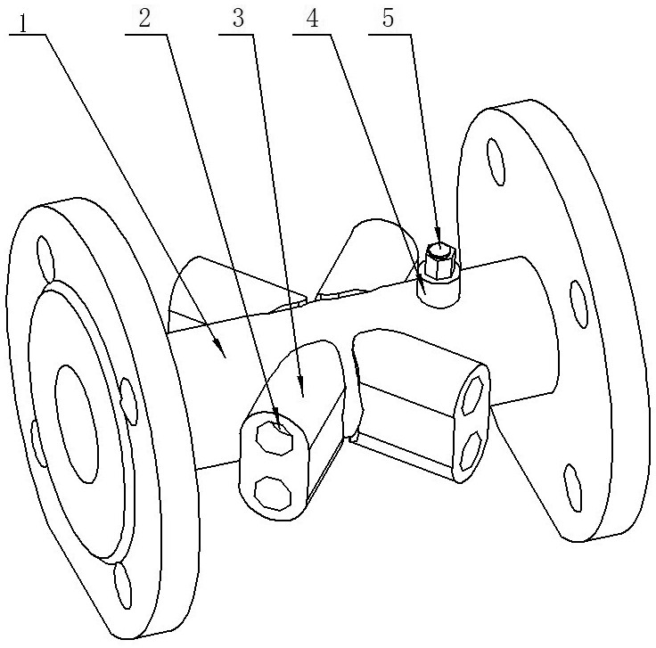
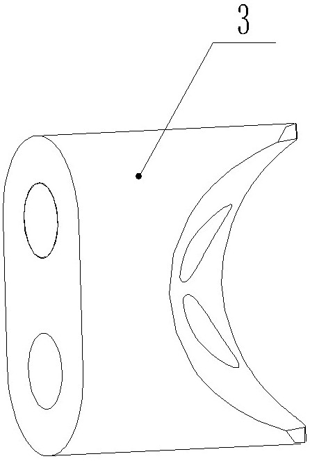
[0030] A cross-type ultrasonic temperature measurement pipe section body structure, comprising a pipe section body 1, a probe mounting seat 3, a probe 2, a temperature sensor 5, and a temperature sensor mounting seat 4; the pipe section body 1 is provided with a probe mounting seat 3 and a temperature sensor mounting seat 4, The probe 2 and the temperature sensor 5 are installed on the probe mounting base 3 and the temperature sensor mounting base 4 respectively; the probe mounting base 3 is provided with a mounting hole, and there is an angle between the center line 6 of the mounting hole and the horizontal line 7, which are not parallel to each other; There are multiple probes, which are divided into upstream probes and downstream probes according to their arrangement positions; the number of upstream probes is equal to the number of downstream...


PUM


Abstract

The invention relates to a cross-type ultrasonic temperature measurement pipe section body structure and a method, and belongs to the technical field of ultrasonic flow measurement and temperature measurement. According to the technical scheme, a probe mounting seat (3) is provided with a mounting hole, an included angle is formed between a center line (6) of the mounting hole and a horizontal line (7), and the mounting hole and the horizontal line are not parallel, wherein the number of the upstream side probes is equal to that of the downstream side probes; one upstream side probe is matched with two downstream side probes in the beam width range of the upstream side probe, one downstream side probe is matched with two upstream side probes in the beam width range of the downstream side probe, ultrasonic waves are transmitted and received, and a plurality of ultrasonic measurement sound paths which are arranged in a crossed mode are formed. The invention has the beneficial effects that one probe is matched with two corresponding probes in the beam width range by changing the angle between the probe mounting hole and the horizontal line, so that the number of effective sound paths on the same pipe section body is greater than or equal to the sum of the number of the probes on the pipe section body. According to the structure, the number of the probes is greatly reduced, so that measurement of more sound paths can be realized on a small caliber.

Description

technical field [0001] The invention relates to a cross-type ultrasonic temperature-measuring pipe segment structure and method, which are used for ultrasonic flowmeters (including liquid and gas flowmeters), ultrasonic water meters, ultrasonic heat meters, etc., and belong to the technical field of ultrasonic flow measurement and temperature measurement. Background technique [0002] At present, the traditional ultrasonic flowmeter measurement pipe section adopts the probe installation hole as a straight hole parallel to the horizontal plane, which is a structural form of one-to-one sound path transmission. In order to meet the requirements of improving measurement accuracy, the only available technology is: increase the number of channels, and convert the measuring instrument from one channel to multiple. Since the number of channels is proportional to the number of probes, which is 1:2, the number of channels The more the number, the more probes. The problem of the prior...

Claims


Application Information

Patent Timeline
IPC IPC(8): G01F15/18G01F1/66
CPCG01F15/185G01F1/66
Inventor 张力新严学智冯宪奎朱向娜李德海
Owner HUIZHONG INSTR
Features
  • R&D
  • Intellectual Property
  • Life Sciences
  • Materials
  • Tech Scout
  • Unparalleled Data Quality
  • Higher Quality Content
  • 60% Fewer Hallucinations
Learn More