Multifunctional clinical operation rack device for hand and foot surgery department

A multi-functional, hands-and-foot technology, applied in the direction of operating tables, surgery, medical science, etc., can solve the problems of lack of auxiliary functions of limbs, obstacles, and unfavorable operations.

Active Publication Date: 2021-12-10
XIAN HONGHUI HOSPITAL
View PDF11 Cites 0 Cited by
  • Summary
  • Abstract
  • Description
  • Claims
  • Application Information

AI Technical Summary

Problems solved by technology

[0002] Hand and foot surgery belongs to the field of surgery and is one of various medical departments. During hand, foot and limb surgery, patients are usually placed on the operating table so that medical staff can better to treat patients; the operating table in the prior art is usually a universal overall operating table, which is suitable for most parts of the operation, but for the operation of the limbs, especially the leg operation, it lacks specific auxiliary functions. For example, some legs Leg surgery requires the patient's single limb to be tilted

Method used


Image

  • Multifunctional clinical operation rack device for hand and foot surgery department
  • Multifunctional clinical operation rack device for hand and foot surgery department
  • Multifunctional clinical operation rack device for hand and foot surgery department

Examples


Embodiment 1

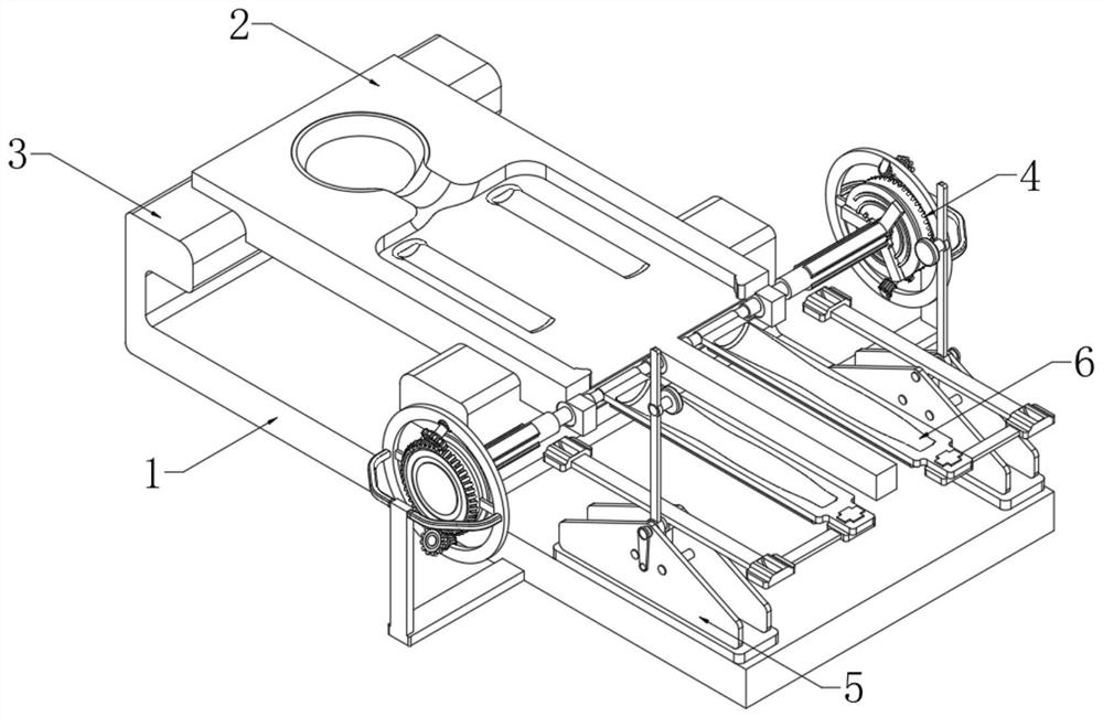
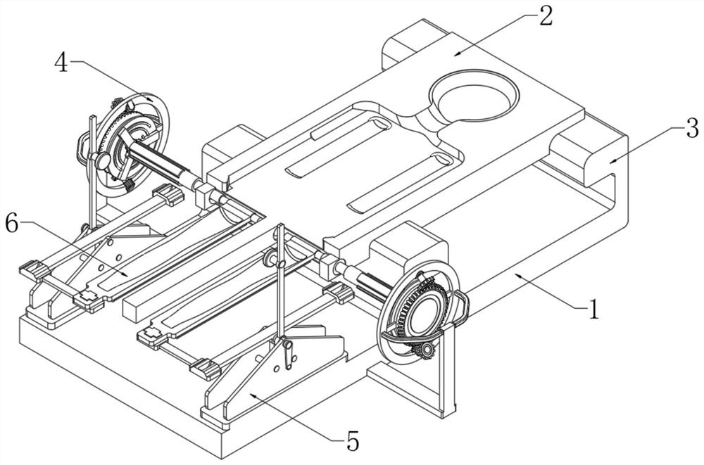
[0038] see Figure 1-5, a multi-functional operating bench device for hand and foot surgery, including a base 1, the upper side of one end of the base 1 is fixedly connected with a main platform body 2 through a support seat 3, and the front end of the main platform body 2 is movably connected with a leg for placement Frame 6, the two ends of the front side of the leg placement frame 6 are respectively flexibly connected to the upper side of the base 1 through the locking assembly 4, and the two ends of the rear side of the leg placement frame 6 are respectively flexibly connected to the upper side of the base 1 through the lifting component 5;

[0039] The front end of the main table body 2 is fixedly connected with a mounting block 9, and the center of the mounting block 9 is provided with a fixed shaft 7. The locking column 8; the end of the leg placing frame 6 is fixedly connected with a damping sleeve 602, and the damping sleeve 602 is sleeved on the surface of the fixed ...

Embodiment 2

[0042] Such as Figure 4-7 As shown, the differences based on Embodiment 1 are:

[0043] The lifting assembly 5 includes a fixed seat 501, which is fixedly connected to the upper side of the base 1, and two sets of mounting plates 502 are fixedly connected to the fixed seat 501; the two sets of mounting plates 502 are fixedly connected through the mounting shaft 5021, and the mounting shaft 5021 There are two barrier columns 5022 arranged symmetrically below;

[0044] A linkage rod 503 is rotatably connected to the installation shaft 5021, and a barrier rod 5031 is fixedly connected to the lower part of the center of the linkage rod 503, and the barrier rod 5031 is movably arranged between the two barrier columns 5022; the two ends of the linkage rod 503 are respectively fixedly connected to a linkage block 508, On the installation shaft 5021, a hand pressure lever 504 is also rotatably connected;

[0045] The front side of the upper end of the hand lever 504 is fixedly conn...

Embodiment 3

[0050] Such as Figure 8-13 As shown, based on embodiment 1-2, what is different is:

[0051] The locking assembly 4 includes a fixed ring 403, the two ends of the rear side of the fixed ring 403 are fixedly connected with a fixed frame 402, the center of the fixed frame 402 is fixedly connected to the upper end of the support frame 401, and the support frame 401 is fixedly connected to both sides of the base 1; the fixed ring 403 A conical wheel 405 is arranged in the center, and the center of the rear side of the conical wheel 405 is fixedly connected with a wheel shaft 4051. The outer edge of the wheel shaft 4051 is movably sleeved with a limit collar 412, and the two sides of the limit collar 412 are respectively connected The frame 411 is fixedly connected with the fixing ring 403;

[0052] The upper and lower sides of the conical wheel 405 are meshed with linkage gears 406 respectively. The axis of the linkage gear 406 is fixedly connected with a drive motor 407, and th...


PUM


Abstract

The invention discloses a multifunctional clinical operation rack device for the hand and foot surgery department, and belongs to the technical field of medical equipment. The multifunctional clinical operation rack device for the hand and foot surgery department comprises a base, wherein a main table body is fixedly connected to the upper side of one end of the base through a supporting seat, a leg placing frame is movably connected to the front end of the main table body, and the two ends of the front side of the leg placing frame are movably connected with the upper side of the base through locking assemblies correspondingly; the two ends of the rear side of the leg placing frame are movably connected with the upper side of the base through lifting assemblies correspondingly; and mounting blocks are fixedly connected to the front end of the main table body, two sets of fixing shafts are arranged in the centers of the mounting blocks, one ends of the two sets of fixing shafts are rotationally connected to the centers of the mounting blocks, and locking columns are clamped to the other ends of the two sets of fixing shafts in a sliding mode. The problems that in the prior art, an operating table cannot obliquely position the legs of a patient, and a wound part cannot be reasonably displayed at the angle where medical staff can conveniently observe and operate the operating table are solved.

Description

technical field [0001] The invention belongs to the technical field of medical equipment, and in particular relates to a multifunctional operating platform device used in clinical hand and foot surgery. Background technique [0002] Hand and foot surgery belongs to the field of surgery and is one of various medical departments. During hand, foot and limb surgery, patients are usually placed on the operating table so that medical staff can treat patients better; the operating table in the prior art is usually The universal overall operating table is suitable for surgery on most parts, but it lacks specific auxiliary functions for limb surgery, especially leg surgery. Reasonable display is at an angle where the medical staff can easily observe and operate to assist the successful operation of the leg, but the universal operating table cannot be realized, because when the two legs are placed naturally, the other leg will perform the required operation. The legs of the operatio...

Claims


Application Information

Patent Timeline
IPC IPC(8): A61G13/12A61G13/00
CPCA61G13/1245A61G13/00A61G13/128
Inventor 夏雷
Owner XIAN HONGHUI HOSPITAL
Why Eureka
Try Eureka