

Smart factory firefighting inspection system
An inspection system and factory technology, applied in fire rescue and other directions, can solve problems such as increased loss, foreign object collision, and prolong fire extinguishing time, and achieve the effect of facilitating later maintenance, improving response ability, and reducing fire extinguishing time.
- Summary
- Abstract
- Description
- Claims
- Application Information
AI Technical Summary
Problems solved by technology
Method used
Image

Examples
Embodiment 1
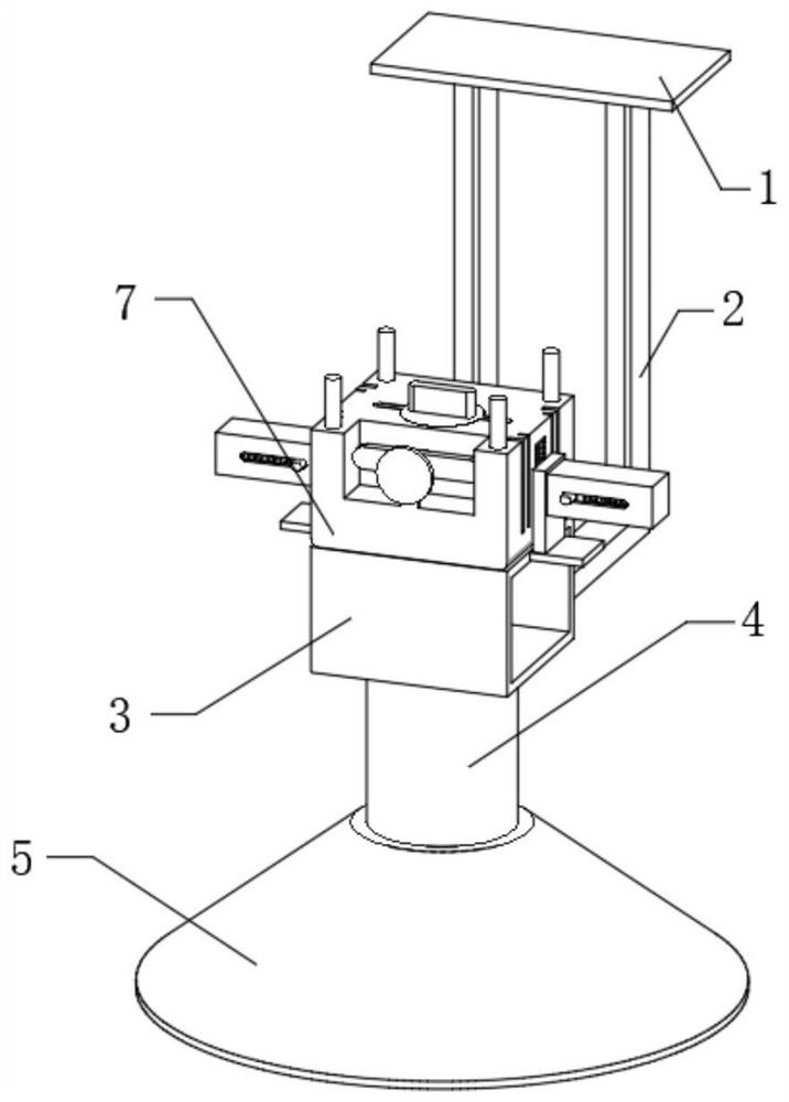
[0036] The embodiment of the present invention discloses a smart factory fire inspection system, such as Figure 1-10 shown, including:
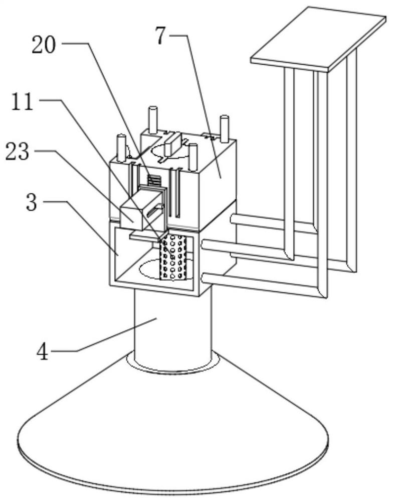
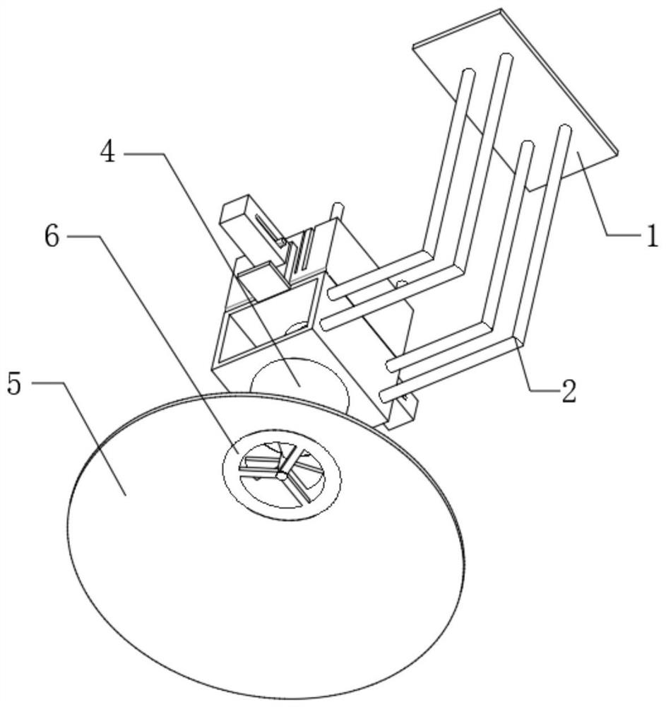
[0037] The overall support plate 1 of the device, the overall support plate 1 of the device is fixedly connected to the ceiling by bolts, the bottom of the overall support plate 1 of the device is fixedly connected with a support fixed rod 2, and the end of the support fixed rod 2 away from the overall support plate 1 of the device is fixedly connected with a ventilation The top of the square pipe 3 and the ventilating square pipe 3 are fixedly installed with the inspection system sensor mounting seat 7, and the top of the inspection system sensor mounting seat 7 is provided with a circular clamping groove 10;
[0038] Vertical round pipe 4, vertical round pipe 4 is fixedly connected to the bottom of ventilating square pipe 3, and the bottom of vertical round pipe 4 is fixedly connected with horn collecting cover 5;
[0039] The air flow fa...
Embodiment 2
[0052] The embodiment of the present invention discloses a smart factory fire inspection system, such as Figure 1-10 shown, including:
[0053] The overall support plate 1 of the device, the overall support plate 1 of the device is fixedly connected to the ceiling by bolts, the bottom of the overall support plate 1 of the device is fixedly connected with a support fixed rod 2, and the end of the support fixed rod 2 away from the overall support plate 1 of the device is fixedly connected with a ventilation The top of the square pipe 3 and the ventilating square pipe 3 are fixedly installed with the inspection system sensor mounting seat 7, and the top of the inspection system sensor mounting seat 7 is provided with a circular clamping groove 10;
[0054] Vertical round pipe 4, vertical round pipe 4 is fixedly connected to the bottom of ventilating square pipe 3, and the bottom of vertical round pipe 4 is fixedly connected with horn collecting cover 5;
[0055] The air flow fa...
PUM
 Abstract
Description
Claims
Application Information