Intelligent power distribution cabinet with remote monitoring function

A technology for remote monitoring and power distribution cabinets, which can be used in substations/distribution device enclosures, fire rescue, etc., and can solve the problems of insufficient protection of intelligent power distribution cabinets.

Inactive Publication Date: 2021-06-04
丁翠芳
View PDF12 Cites 4 Cited by
  • Summary
  • Abstract
  • Description
  • Claims
  • Application Information

AI Technical Summary

Problems solved by technology

[0004] Now in order to better manage power distribution, an intelligent power distribution cabinet with remote monitoring function is designed, but the existing intelligent power distribution cabinet only has a smoke sensing function for fire, and the smoke is sensed and passed to the management center for timely processing. Cabinet protection is not comprehensive enough

Method used


Image

  • Intelligent power distribution cabinet with remote monitoring function
  • Intelligent power distribution cabinet with remote monitoring function
  • Intelligent power distribution cabinet with remote monitoring function

Examples


Embodiment 1

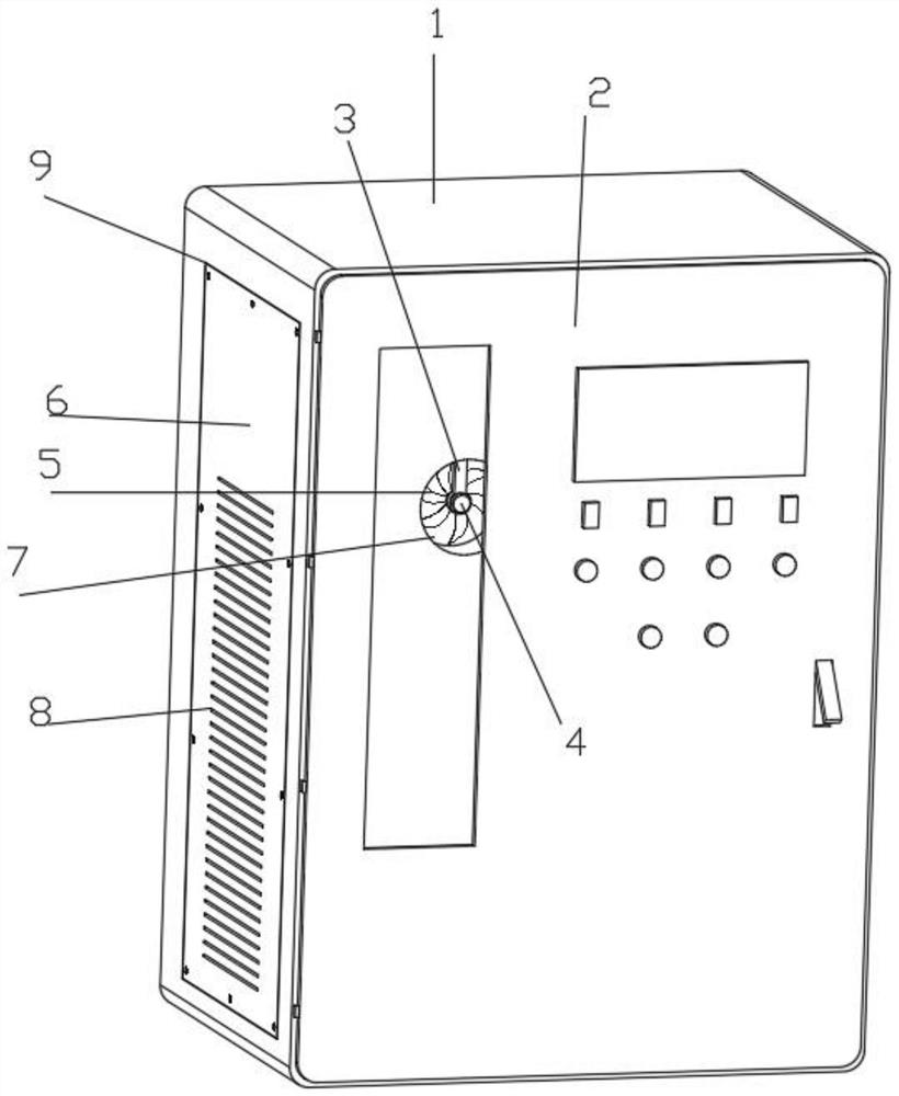
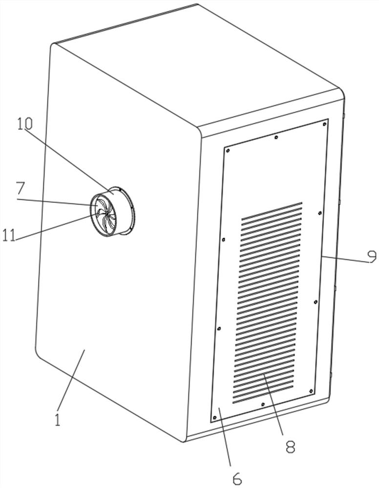
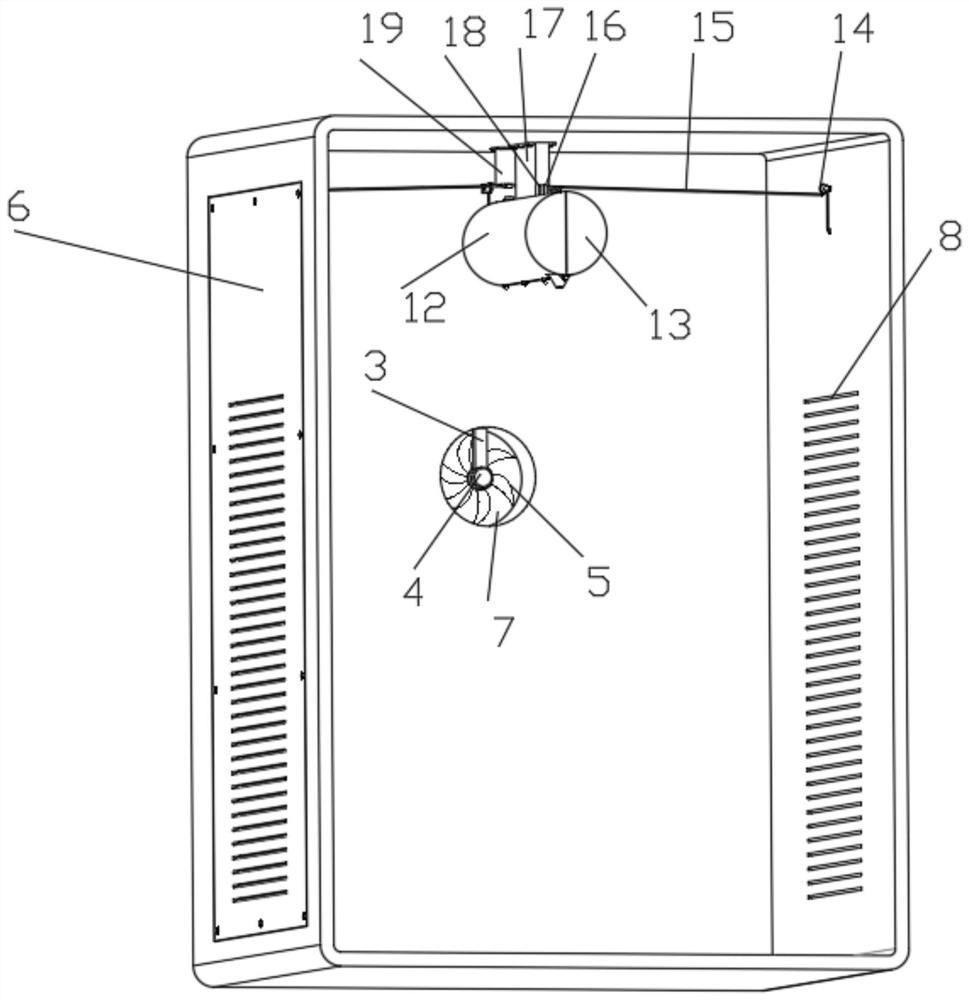
[0033] Such as figure 1 , 2 , 3, 5, 8 and 10 show a kind of intelligent power distribution cabinet with remote monitoring function, including intelligent power distribution cabinet body 1, door panel 2 and aerosol fire extinguisher 23, the front side wall of intelligent power distribution cabinet body 1 is hinged A door panel 2 equipped with a glass observation window is connected with the lock, a nozzle 231 for spraying aerosol is fixedly connected to the bottom front end of the aerosol fire extinguisher 23, and a nozzle 231 for opening the aerosol fire extinguisher 23 is fixedly connected to the top of the rear end of the aerosol fire extinguisher 23. The button 232, the rear end of the aerosol fire extinguisher 23 is fixedly connected with the pull ring 233, the two outer walls of the intelligent power distribution cabinet body 1 are provided with grooves 9, and the groove 9 is fixedly connected with the side plate 6 by bolts, the side plate 6 and the intelligent power dist...

Embodiment

[0034] Example door panel 2

[0035] The door panel 2 of the embodiment is a further improvement on the body 1 of the intelligent distribution cabinet of the embodiment.

[0036] As shown in the figure, the straight plate 3, the servo motor 4, the fan blade 5, the side plate 6, and the round baffle 7 are installed, the smart power distribution cabinet body 1 is provided with a starting structure for starting the aerosol fire extinguisher 23 on the rear side of the installation top plate 17, The starting structure includes installation cylinder 19, second steel rope 25, second fixed pulley 26, third fixed pulley 27, electromagnet 28, third spring 29, T-shaped iron rod 30 and hook 31, and the inner top of installation cylinder 19 is fixedly connected There are electromagnets 28 and a third spring 29, the bottom of the third spring 29 is fixedly connected with a T-shaped iron rod 30 that fits and slides with the inner wall of the installation cylinder 19, and the bottom of the T-...


PUM


Abstract

The invention discloses an intelligent power distribution cabinet with a remote monitoring function, and relates to the technical field of power distribution cabinets. The intelligent power distribution cabinet comprises an intelligent power distribution cabinet body, grooves are formed in the two outer walls of the intelligent power distribution cabinet body, and side plates are fixedly connected in the grooves through bolts; the side plate and the side wall of the intelligent power distribution cabinet body are uniformly provided with first air inlet inclined holes used for air inlet. The air outlet structure comprises an installation straight plate (3), a servo motor (4), fan blades (5) and an air outlet pipe (10). The air outlet pipe (10) is fixedly installed at an air outlet hole in the rear side wall of the intelligent power distribution cabinet body (1), the inner top of the air outlet pipe (10) is fixedly connected with the installation straight plate (3), the installation straight plate (3) is fixedly provided with the servo motor (4), and the output end of the servo motor (4) is fixedly connected with the fan blades (5). The fire can be controlled in time, and the intelligent power distribution cabinet is comprehensively protected.

Description

technical field [0001] The invention relates to the technical field of power distribution cabinets, in particular to an intelligent power distribution cabinet with a remote monitoring function. Background technique [0002] The power distribution cabinet (box) is divided into power distribution cabinet (box), lighting distribution cabinet (box), metering cabinet (box), and is the final equipment of the power distribution system. The power distribution cabinet is a general term for the motor control center. The power distribution cabinet is used in the occasions where the load is relatively scattered and there are few circuits; the motor control center is used in the occasions where the load is concentrated and there are many circuits. They distribute the electric energy of a certain circuit of the upper-level power distribution equipment to the nearest load. This level of equipment shall provide protection, monitoring and control of the load. [0003] The transmission and...

Claims


Application Information

Patent Timeline
Patent Type & Authority Applications(China)
IPC IPC(8): H02B1/30A62C5/033
CPCH02B1/30A62C5/033
Inventor 不公告发明人
Owner 丁翠芳
Why Eureka
Try Eureka