
Truss type modular wind power blade

A wind turbine blade and modular technology, which is applied to wind power generation, wind turbines in the same direction as the wind, and wind turbines, can solve the problems affecting the service life of wind turbine blades, poor stability of wind turbine blades, and complex stress at the connection position. The effect of unstable manufacturing quality, avoiding fatigue cracking, and improving overall stability

Active Publication Date: 2021-12-10
NEWTECH GRP CO LTD
View PDF7 Cites 2 Cited by
  • Summary
  • Abstract
  • Description
  • Claims
  • Application Information

AI Technical Summary

Problems solved by technology

[0002] The research on wind power blades at home and abroad has been constantly exploring, especially foreign countries have done many researches on modular blades. At present, the technical characteristics of the modular blade structure scheme developed by the industry, the modular structure is designed along the axial direction. There is a problem of sudden change in stiffness at the position, the stress at the connection position is complex, and the assembly is also relatively complicated, which leads to the failure of the connection position. At the same time, the segmental connection position is mechanically connected to assist plugging, and the connection reliability is not strong, which leads to poor overall stability of the wind turbine blades and seriously affects The service life of wind turbine blades

Method used


Image

  • Truss type modular wind power blade
  • Truss type modular wind power blade
  • Truss type modular wind power blade

Examples


Embodiment Construction

[0042] The following will clearly and completely describe the technical solutions in the embodiments of the present invention with reference to the accompanying drawings in the embodiments of the present invention. Obviously, the described embodiments are only some, not all, embodiments of the present invention.

[0043] It should be noted that when an element is referred to as being “fixed” to another element, it can be directly on the other element or there can also be an intervening element. When an element is referred to as being "connected to" another element, it can be directly connected to the other element or intervening elements may also be present. The terms "vertical," "horizontal," "left," "right," and similar expressions are used herein for purposes of illustration only and are not intended to represent the only embodiments.

[0044] Unless otherwise defined, all technical and scientific terms used herein have the same meaning as commonly understood by one of ordi...


PUM


Abstract

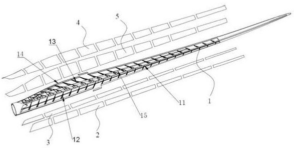
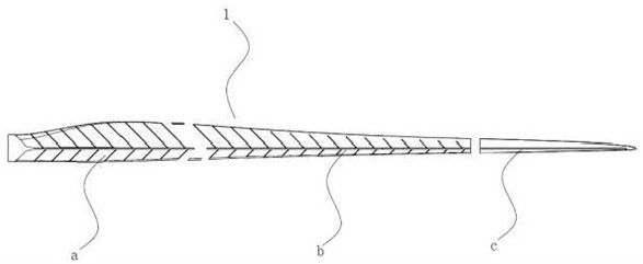
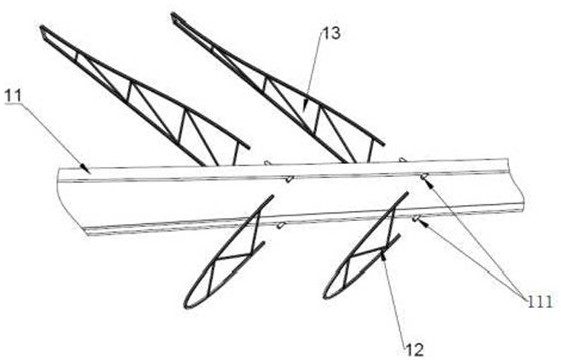
The invention relates to the technical field of wind power generation equipment, in particular to a truss type modular wind power blade. The truss type modular wind power blade comprises a blade truss frame, a front edge shell module and a rear edge shell module; the blade truss frame comprises a main beam, a plurality of front edge supporting trusses and a plurality of rear edge supporting trusses, the front edge supporting trusses and the rear edge supporting trusses are distributed in the length direction of the main beam in a staggered mode, and rear edge beams and rear edge small I-shaped beams are arranged on the corresponding sides of the rear edge trusses; the front edge shell module comprises PS front edge shells arranged on the windward sides of the front edge supporting trusses and SS front edge shells arranged on the leeward sides of the front edge supporting trusses; and the rear edge shell module comprises PS rear edge shells arranged on the windward sides of the rear edge supporting frames and SS rear edge shells arranged on the leeward sides of the rear edge supporting frames. The front and rear edge shell modules are connected with the main beam through the front and rear edge supporting trusses, the front and rear edge supporting trusses and the main beam are designed to form a certain angle, internal force borne by the main beam is transmitted to the trusses and released to the front edge and the rear edge, finally, the force is transmitted to the blade root, an overall stable structure is formed, and the overall stability of the wind power blade is improved.

Description

technical field [0001] The invention relates to the technical field of wind power generation equipment, in particular to a truss type modular wind power blade. Background technique [0002] The research on wind power blades at home and abroad has been constantly exploring, especially foreign countries have done many researches on modular blades. At present, the technical characteristics of the modular blade structure scheme developed by the industry, the modular structure is designed along the axial direction. There is a problem of sudden change in stiffness at the position, the stress at the connection position is complex, and the assembly is also relatively complicated, which leads to the failure of the connection position. At the same time, the segmental connection position is mechanically connected to assist plugging, and the connection reliability is not strong, which leads to poor overall stability of the wind turbine blades and seriously affects The service life of wi...

Claims


Application Information

Patent Timeline
Patent Type & Authority Applications(China)
IPC IPC(8): F03D1/06
CPCF03D1/0675Y02P70/50
Inventor 谈昆伦刘叶霖杜秋萍白高宇曹磊
Owner NEWTECH GRP CO LTD
Learn More